
Introduction
Writing program for the microcontroller mainly consists of giving
instructions (commands) in that order in which they should be executed later in
order to carry out specific task. As electronics can not “understand” what for
example instruction “if the push button is pressed- turn the light on” means,
then a certain number of more simpler and precisely defined orders that decoder
can recognise must be used. All commands are known as INSTRUCTION SET. All
microcontrollers compatibile with the 8051 have in total of 255 instructions,
i.e. 255 different words available for program writing.
At first sight, it is imposing number of odd signs that must be known by
heart. However, It is not so complicated as it looks like. Many instructions
are considered to be “different”, even though they perform the same operation,
so there are only 111 truly different commands. For example: ADD A,R0, ADD A,R1,
... ADD A,R7 are instructions that perform the same operation (additon of the
accumulator and register) but since there are 8 such registers, each
instruction is counted separately! Taking into account that all instructions
perform only 53 operations ( addition, subtraction, copy etc.) and most of them
are rarely used in practice, there are actually 20-30 shortened forms needed to
be known, which is acceptable.
Types of instructions
Depending on operation they perform, all instructions are divided in several
groups:
LOOP (if the number in the
accumulator is not 0, jump to address specified as LOOP )
Another part of instruction, called OPERAND is separated from mnemonic at
least by one empty space and defines data being processed by instructions. Some
instructions have no operand, some have one, two or three. If there is more
than one operand in instruction, they are separated by comma. For example:
LOOP )
Arithmetic instructions
These instructions perform several basic operations ( addition, subtraction,
division, multiplication etc.) After execution, the result is stored in the
first operand. For example:
There are two kinds of these instructions:
Unconditional jump instructions: after their execution a jump to a new location from where the program continues execution is executed.
Conditional jump instructions: if some condition is met - a jump is executed. Otherwise, the program normally proceeds with the next instruction.
- Arithmetic Instructions
- Branch Instructions
- Data Transfer Instructions
- Logical Instructions
- Logical Instructions with bits
INC R1 -
Means: Increment R1 (increment register R1)LJMP LAB5 - Means: Long Jump
LAB5 (long jump to address specified as LAB5)JNZ LOOP - Means: Jump if
Not Zero RET -
(return from sub-routine)JZ TEMP - (if the number in
the accumulator is not 0, jump to address specified as TEMP)ADD A,R3 - (add R3 and
accumulator)CJNE A,#20,LOOP - (compare
accumulator with 20. If they are not equal, jump to address specified as Arithmetic instructions
ADD A,R1
- The result of addition (A+R1) will be stored in the accumulator.
Arithmetical
Instructions
|
|||
Mnemonic
|
Description
|
Byte Number
|
Oscillator
Period
|
ADD A,Rn
|
Add R Register to
accumulator
|
1
|
1
|
ADD A,Rx
|
Add directly
addressed Rx Register to accumulator
|
2
|
2
|
ADD A,@Ri
|
Add indirectly
addressed Register to accumulator
|
1
|
1
|
ADD A,#X
|
Add number X to
accumulator
|
2
|
2
|
ADDC A,Rn
|
Add R Register with
Carry bit to accumulator
|
1
|
1
|
ADDC A,Rx
|
Add directly
addressed Rx Register with Carry bit to accumulator
|
2
|
2
|
ADDC A,@Ri
|
Add indirectly
addressed Register with Carry bit to accumulator
|
1
|
1
|
ADDC A,#X
|
Add number X with
Carry bit to accumulator
|
2
|
2
|
SUBB A,Rn
|
Subtruct R Register
with borrow from accumulator
|
1
|
1
|
SUBB A,Rx
|
Subtruct directly
addressed Rx Register with borrow from accumulator
|
2
|
2
|
SUBB A,@Ri
|
Subtruct indirectly
addressed Register with borrow from accumulator
|
1
|
1
|
SUBB A,#X
|
Subtruct number X
with borrow from accumulator
|
2
|
2
|
INC A
|
Increment
accumulator by 1
|
1
|
1
|
INC Rn
|
Increment R
Register by 1
|
1
|
1
|
INC Rx
|
Increment directly
addressed Rx Register by 1
|
2
|
2
|
INC @Ri
|
Increment
indirectly addressed Register by 1
|
1
|
1
|
DEC A
|
Decrement accumulator
by 1
|
1
|
1
|
DEC Rn
|
Decrement R
Register by 1
|
1
|
1
|
DEC Rx
|
Decrement directly
addressed Rx Register by 1
|
2
|
2
|
DEC @Ri
|
Decrement
indirectly addressed Register by 1
|
1
|
1
|
INC DPTR
|
Increment Data
Pointer by 1
|
1
|
3
|
MUL AB
|
Multiply number in
accumulator by B register
|
1
|
5
|
DIV AB
|
Divide number in
accumulator by B register
|
1
|
5
|
DA A
|
Decimal adjustment
of accumulator according to BCD code
|
1
|
1
|
Unconditional jump instructions: after their execution a jump to a new location from where the program continues execution is executed.
Conditional jump instructions: if some condition is met - a jump is executed. Otherwise, the program normally proceeds with the next instruction.
Branch
Instruction
|
|||
Mnemonic
|
Description
|
Byte Number
|
Oscillator
Period
|
ACALL adr11
|
Call subroutine
located at addreess within 2 K byte Program Memory space
|
2
|
3
|
LCALL adr16
|
Call subroutine
located at any address within 64 K byte Program Memory space
|
3
|
4
|
RET
|
Return from
subroutine
|
1
|
4
|
RETI
|
Return from
interrupt routine
|
1
|
4
|
AJMP adr11
|
Jump to address
located within 2 K byte Program Memory space
|
2
|
3
|
LJMP adr16
|
Jump to any address
located within 64 K byte Program Memory space
|
3
|
4
|
SJMP rel
|
Short jump (from
–128 to +127 locations in relation to first next instruction).
|
2
|
3
|
JC rel
|
Jump if Carry bit
is set. Short jump.
|
2
|
3
|
JNC rel
|
Jump if Carry bit
is cleared. Short jump.
|
2
|
3
|
JB bit,rel
|
Jump if addressed
bit is set. Short jump.
|
3
|
4
|
JBC bit,rel
|
Jump if addressed
bit is set and clear it. Short jump.
|
3
|
4
|
JMP @A+DPTR
|
Indirect jump. Jump
address is obtained by addition of accumulator and DPTR Register
|
1
|
3
|
JZ rel
|
Jump if accumulator
is 0. Short jump.
|
2
|
3
|
JNZ rel
|
Jump if accumulator
is not 0. Short jump.
|
2
|
3
|
CJNE A,Rx,rel
|
Compare accumulator
and directly addressed Register Rx. Jump if they are different. Short jump.
|
3
|
4
|
CJNE A,#X,rel
|
Compare accumulator
with number X. Jump if they are different. Short jump.
|
3
|
4
|
CJNE Rn,#X,rel
|
Compare Register R
with number X. Jump if they are different. Short jump.
|
3
|
4
|
CJNE @Ri,#X,rel
|
Compare indirectly
addressed register with number X. Jump if they are different. Short jump.
|
3
|
4
|
DJNZ Rn,rel
|
Decrement R
Register by 1. Jump if the result is not 0. Short jump.
|
2
|
3
|
DJNZ Rx,rel
|
Decrement directly
addressed Register Rx by 1. Jump if the result is not 0. Short jump.
|
3
|
4
|
NOP
|
No operation
|
1
|
1
|
Data Transfer Instructions
These instructions move the content of one register to another one. The
register which content is moved remains unchanged. If they have the suffix “X”
(MOVX), the data is exchanged with external memory.
Data Transfer
Instruction
|
|||
Mnemonic
|
Description
|
Byte Number
|
Cycle Number
|
MOV A,Rn
|
Move R register to
accumulator
|
1
|
1
|
MOV A,Rx
|
Move directly
addressed Rx register to accumulator
|
2
|
2
|
MOV A,@Ri
|
Move indirectly
addressed register to accumulator
|
1
|
1
|
MOV A,#X
|
Move number X to
accumulator
|
2
|
2
|
MOV Rn,A
|
Move accumulator to
R register
|
1
|
1
|
MOV Rn,Rx
|
Move directly
addressed Rx register to R register
|
2
|
2
|
MOV Rn,#X
|
Move number X to R
register
|
2
|
2
|
MOV Rx,A
|
Move accumulator to
directly addressed Rx register
|
2
|
2
|
MOV Rx,Rn
|
Move R register to
directly addressed Rx register
|
2
|
2
|
MOV Rx,Ry
|
Move directly
addressed register Ry to directly addressed Rx register
|
3
|
3
|
MOV Rx,@Ri
|
Move indirectly
addressed register to directly addressed Rx register
|
2
|
2
|
MOV Rx,#X
|
Move number X to
directly addressed Rx register
|
3
|
3
|
MOV @Ri,A
|
Move accumulator to
indirectly addressed register
|
1
|
1
|
MOV @Ri,Rx
|
Move directly
addressed Rx register to indirectly addressed register
|
2
|
2
|
MOV @Ri,#X
|
Store number X in
indirectly addressed register
|
2
|
2
|
MOV DPTR,#X
|
Store number X in
Data Pointer
|
3
|
3
|
MOVC A,@A+DPTR
|
Move register from
Program Memory to accumulator (address= A+DPTR)
|
1
|
3
|
MOVC A,@A+PC
|
Move register from
Program Memory to accumulator (address= A+PC)
|
1
|
3
|
MOVX A,@Ri
|
Move data from
external memory to accumulator (8-bit address)
|
1
|
2
|
MOVX A,@DPTR
|
Move data from
external memory to accumulator (16- bit address)
|
1
|
2
|
MOVX @Ri,A
|
Move accumulator to
external memory register (8-bit address)
|
1
|
2
|
MOVX @DPTR,A
|
Move accumulator to
external memory register (16-bit address)
|
1
|
2
|
PUSH Rx
|
Push directly
addressed Rx register on Stack
|
2
|
2
|
POP Rx
|
Pop data from
Stack. Store it in directly addressed Rx register
|
2
|
2
|
XCH A,Rn
|
Exchange
accumulator with R register
|
1
|
1
|
XCH A,Rx
|
Exchange
accumulator with directly addressed Rx register
|
2
|
2
|
XCH A,@Ri
|
Exchange
accumulator with indirectly addressed register
|
1
|
1
|
XCHD A,@Ri
|
Exchange 4 lower
bits in accumulator with indirectly addressed register
|
1
|
1
|
Logical Instruction
These instructions perform logical operations between
corresponding bits of two registers. After execution, the result is stored in
the first operand.
Logical
Instructions
|
|||
Mnemonic
|
Description
|
Byte Number
|
Cycle Number
|
ANL A,Rn
|
Logical AND between
accumulator and R register
|
1
|
1
|
ANL A,Rx
|
Logical AND between
accumulator and directly addressed register Rx
|
2
|
2
|
ANL A,@Ri
|
Logical AND between
accumulator and indirectly addressed register
|
1
|
1
|
ANL A,#X
|
Logical AND between
accumulator and number X
|
2
|
2
|
ANL Rx,A
|
Logical AND between
accumulator and directly addressed register Rx
|
2
|
2
|
ANL Rx,#X
|
Logical AND between
directly addressed register Rx and number X
|
3
|
3
|
ORL A,Rn
|
Logical OR between
accumulator and R register
|
1
|
1
|
ORL A,Rx
|
Logical OR between
accumulator and directly addressed register Rx
|
2
|
2
|
ORL A,@Ri
|
Logical OR between
accumulator and indirectly addressed register
|
2
|
2
|
ORL Rx,A
|
Logical OR between
accumulator and directly addressed register Rx
|
2
|
2
|
ORL Rx,#X
|
Logical OR between
directly addressed register Rx and number X
|
3
|
3
|
XORL A,Rn
|
Logical exclusive
OR between accumulator and R register
|
1
|
1
|
XORL A,Rx
|
Logical exclusive
OR between accumulator and directly addressed register Rx
|
2
|
2
|
XORL A,@Ri
|
Logical exclusive
OR between accumulator and indirectly addressed register
|
1
|
1
|
XORL A,#X
|
Logical exclusive
OR between accumulator and number X
|
2
|
2
|
XORL Rx,A
|
Logical exclusive
OR between accumulator and directly addressed register Rx
|
2
|
2
|
XORL Rx,#X
|
Logical exclusive
OR between accumulator and directly addressed register Rx and number X
|
3
|
3
|
CLR A
|
Clear accumulator
|
1
|
1
|
CPL A
|
Complement
accumulator (1=0, 0=1)
|
1
|
1
|
SWAP A
|
Swap nibbles in
accumulator (left and right half of one byte)
|
1
|
1
|
RL A
|
Rotate bits in
accumulator left by 1 place
|
1
|
1
|
RLC A
|
Rotate bits in
accumulator left by 1 place through Carry
|
1
|
1
|
RR A
|
Rotate bits in
accumulator right by 1 place
|
1
|
1
|
RRC A
|
Rotate bits In
accumulator right by 1 place through Carry
|
1
|
1
|
Bit Oriented Instructions
Similar to logical instructions, these instructions perform logical operations.
The difference is that these operations are performed on single bits.
Logical
operations on bits
|
|||
Mnemonic
|
Description
|
Byte Number
|
Cycle Number
|
CLR C
|
Clear Carry bit
|
1
|
1
|
CLR bit
|
Clear directly
addressed bit
|
2
|
2
|
SETB C
|
Set Carry bit
|
1
|
1
|
SETB bit
|
Set directly
addressed bit
|
2
|
2
|
CPL C
|
Complement Carry
bit
|
1
|
1
|
CPL bit
|
Complement directly
addressed bit
|
2
|
2
|
ANL C,bit
|
Logical AND between
Carry bit and directly addressed bit
|
2
|
2
|
ANL C,/bit
|
Logical AND between
Carry bit and inverted directly addressed bit
|
2
|
2
|
ORL C,bit
|
Logical OR between
Carry bit and directly addressed bit
|
2
|
2
|
ORL C,/bit
|
Logical OR between
Carry bit and inverted directly addressed bit
|
2
|
2
|
MOV C,bit
|
Move directly
addressed bit to Carry bit
|
2
|
2
|
MOV bit,C
|
Move Carry bit to
directly addressed bit
|
2
|
2
|
Description of all 8051 instructions
The operands listed below are written in shortened forms having the
following meaning :
Syntax: ACALL [subroutine name]
Bytes : 2 (Instruction Code, Address of the subroutine called)
STATUS register flags: No flags are affected.
EXAMPLE:
 Before execution: PC=0123h
After execution: PC=0345h
ADD A,Rn - Add register Rn and accumulator
Syntax: ADD A,Rn
Byte: 1 (Instruction Code)
STATUS register flags: C, OV i ACy
EXAMPLE:

Before execution: A=2Eh (46 dec.) R4=12h (18 dec.)
After execution: A=40h (64 dec.) R4=12h
ADD A,@Ri - Add indirectly addressed register and accumulator
Syntax: ADD A,@Ri
Byte: 1 (Instruction Code)
STATUS register flags: C, OV and AC
EXAMPLE:

Register address: SUM = 4Fh R0=4Fh
Before execution: A= 16h (22 dec.) SUM= 33h (51 dec.)
After execution : A= 49h (73 dec.)
ADD A,Rx - Add directly addressed register Rx and accumulator
Syntax: ADD A, Register name
Bytes: 2 (Instruction Code, Rx Address)
STATUS register flags: C, OV and AC
EXAMPLE:

Before execution: SUM= 33h (51 dec.) A= 16h (22 dec.)
After execution: SUM= 33h (73 dec.) A= 49h (73 dec.)
ADDC A,Rn - Add register Rn, accumulator and Carry bit
Syntax: ADDC A,Rn
Byte: 1 (Instruction Code)
STATUS register flags: C, OV i AC
EXAMPLE:

A -
accumulator
Rn - Rn is one of R registers (R0-R7) in the currently active bank in RAM.
Rx - Rx is any register in RAM with 8-bit address. It can be a general-purpose register or SFR Register (I/O port, control register etc.)
@Ri - Ri is R0 or R1 register in the currently active bank. It contains register.
address - the instruction is referring to.
#X - X is any 8-bit number (0-255).
#X16 - X is any 16-bit number (0-65535).
adr16 - 16-bit address is specified
adr11 - 11-bit address is specified
rel - The address of a close memory location is specified (-128 do +127 rela tive to the current one). Basing on that address,
Asembler computes the value which is added or subtructed to the number which currently stored in the program counter.
bit - Bit address is specified.
C - Carry bit in the status register (register PSW)
ACALL adr11 - Call subroutineRn - Rn is one of R registers (R0-R7) in the currently active bank in RAM.
Rx - Rx is any register in RAM with 8-bit address. It can be a general-purpose register or SFR Register (I/O port, control register etc.)
@Ri - Ri is R0 or R1 register in the currently active bank. It contains register.
address - the instruction is referring to.
#X - X is any 8-bit number (0-255).
#X16 - X is any 16-bit number (0-65535).
adr16 - 16-bit address is specified
adr11 - 11-bit address is specified
rel - The address of a close memory location is specified (-128 do +127 rela tive to the current one). Basing on that address,
Asembler computes the value which is added or subtructed to the number which currently stored in the program counter.
bit - Bit address is specified.
C - Carry bit in the status register (register PSW)
adr11: - Subroutine address
Description: Instruction unconditionally calls a subroutine located
at the specified address. Therefore, the current address and the address of
called subroutine must be within the same 2K byte block of the program memory,
starting from the first byte of the instruction following ACALL.Syntax: ACALL [subroutine name]
Bytes : 2 (Instruction Code, Address of the subroutine called)
STATUS register flags: No flags are affected.
EXAMPLE:

After execution: PC=0345h
ADD A,Rn - Add register Rn and accumulator
A: accumulator
Rn: Any R register (R0-R7)
Description: Instruction adds the number in the accumulator and the
number in register Rn (R0-R7). After addition, the result is stored in the
accumulator.Rn: Any R register (R0-R7)
Syntax: ADD A,Rn
Byte: 1 (Instruction Code)
STATUS register flags: C, OV i ACy
EXAMPLE:

Before execution: A=2Eh (46 dec.) R4=12h (18 dec.)
After execution: A=40h (64 dec.) R4=12h
ADD A,@Ri - Add indirectly addressed register and accumulator
A: accumulator
Ri: Register R0 or R1
Description: Instruction adds number in the accumulator and number in
Rx. The register Rx address is in the Ri register (R0 or R1). After addition,
the result is stored in the accumulator.Ri: Register R0 or R1
Syntax: ADD A,@Ri
Byte: 1 (Instruction Code)
STATUS register flags: C, OV and AC
EXAMPLE:

Register address: SUM = 4Fh R0=4Fh
Before execution: A= 16h (22 dec.) SUM= 33h (51 dec.)
After execution : A= 49h (73 dec.)
ADD A,Rx - Add directly addressed register Rx and accumulator
A: accumulator
Rx: Arbitrary register with address 0 - 255 (0 - FFh)
Description: Instruction adds the accumulator and Rx register. As it
is direct addressing, Rx can be some of SFRs or general-purpose register with
address 0-7 Fh. The result is stored in the accumulator.Rx: Arbitrary register with address 0 - 255 (0 - FFh)
Syntax: ADD A, Register name
Bytes: 2 (Instruction Code, Rx Address)
STATUS register flags: C, OV and AC
EXAMPLE:

Before execution: SUM= 33h (51 dec.) A= 16h (22 dec.)
After execution: SUM= 33h (73 dec.) A= 49h (73 dec.)
ADDC A,Rn - Add register Rn, accumulator and Carry bit
A: accumulator
Rn: any R register (R0-R7)
Description: Instruction adds the accumulator, Carry bit and value in
Rn register (R0-R7). After addition, the result is stored in the accumulator.Rn: any R register (R0-R7)
Syntax: ADDC A,Rn
Byte: 1 (Instruction Code)
STATUS register flags: C, OV i AC
EXAMPLE:

Before execution: A= C3h (195 dec.) R0= AAh (170 dec.) C=1
After execution: A= 6Eh (110 dec.) AC=0, C=1, OV=1
ADD A,#X - Add accumulator and number X
Syntax: ADD A,#X
Bytes: 2 (Instruction Code, Constant X)
STATUS register flags: C, OV i AC
EXAMPLE:

Before execution: A= 16h (22 dec.)
After execution: A= 49h (73 dec.)
ADDC A,Rx - Add accumulator, directly addressed register Rx and Carry bit
Syntax: ADDC A, register address
Bytes: 2 (Instruction Code, Address Rx)
STATUS register flags: C, OV i AC
EXAMPLE:

Before execution: A= C3h (195 dec.) TEMP = AAh (170 dec.) C=1
After execution: A= 6Eh (110 dec.) AC=0, C=1, OV=1
ADDC A,@Ri - Add Carry bit, accumulator and indirectly addressed register Rx
Syntax: ADDC A,@Ri
Byte: 1 (Instruction Code)
STATUS register flags: C, OV i AC
EXAMPLE:

Register address: SUM = 4Fh R0=4Fh
Before execution: A= C3h (195 dec.) SUM = AAh (170 dec.) C=1
After execution: A= 6Eh (110 dec.) AC=0, C=1, OV=1
ADDC A,#X - Add accumulator, number X and Carry bit
Syntax: ADDC A,#X
Bytes: 2 (Instruction Code, Constant X)
STATUS register flags: C, OV i AC
EXAMPLE:

Before execution: A= C3h (195 dec.) C=1
After execution: A= 6Dh (109 dec.) AC=0, C=1, OV=1
AJMP adr11 - Jump to address
Syntax: AJMP address (label)
Bytes: 2 (Instruction Code, Jump Address)
STATUS register flags: No flags are affected.
EXAMPLE:

Before execution: PC=0345h SP=07h
After execution: PC=0123h SP=09h
ANL A,Rn - Logical-AND operation between accumulator and Register Rn
Syntax: ANL A,Rn
Byte: 1 (Instruction Code)
STATUS register flags: No flags are affected.
EXAMPLE:

Before execution: A= C3h (11000011 Bin.)
R5= 55h (01010101 Bin.)
After execution: A= 41h (01000001 Bin.)
ANL A,Rx - Logical-AND operation between accumulator and directly addressed register
Syntax: ANL A,Rx
Byte: 2 (Instruction Code, Constant X)
STATUS register flags: No flags are affected.
EXAMPLE:

Before execution: A= C3h (11000011 Bin.)
MASK= 55h (01010101 Bin.)
After execution: A= 41h (01000001 Bin.)
ANL A,@Ri - Logical-AND operation between accumulator and indirectly addressed register
Syntax: ANL A,@Ri
Byte: 1 (Instruction Code)
STATUS register flags: No flags are affected.
EXAMPLE:

Register address SUM = 4Fh R0=4Fh
Before execution: A= C3h (11000011 Bin.)
R0= 55h (01010101 Bin.)
After execution: A= 41h (01000001 Bin.)
ANL A,#X - Logical-AND operation between accumulator and number X
Syntax: ANL A,#X
Bytes: 2 (Instruction Code, Constant X)
STATUS register flags: No flags are affected.
EXAMPLE:

Before execution: A= C3h (11000011 Bin.)
After execution: A= 41h (01000001 Bin.)
ANL Rx,A - Logical-AND operation between directly addressed register Rx and accumulator
Syntax: ANL register address ,A
Bytes: 2 (Instruction Code, Address Rx)
STATUS register flags: No flags are affected.
EXAMPLE:

Before execution: A= C3h (11000011 Bin.)
MASK= 55h (01010101 Bin.)
After execution: MASK= 41h (01000001 Bin.)
ANL Rx,#X - Logical-AND operation between number X and directly addressed register Rx
Syntax: ANL register address ,#X
Bytes: 3 (Instruction Code, Address Rx, Constant X)
STATUS register flags: No flags are affected.
EXAMPLE:

Before execution: X= C3h (11000011 Bin.) MASK= 55h (01010101 Bin.) After execution: MASK= 41h (01000001 Bin.)
ANL C,bit - Logical-AND operation between bit and Carry bit
Syntax: ANL C, Bit Address
Bytes: 2 (Instruction Code, Bit Address)
STATUS register flags: C
EXAMPLE:

Before execution: ACC= 43h (01000011 Bin.)
C=1
After execution: ACC= 43h (01000011 Bin.)
C=0
ANL C,/bit - Logical-AND opertaion between complement of bit and Carry bit
Syntax: ANL C,/[bit address]
Bytes: 2 (Instruction Code, Bit Address)
STATUS register flags: No flags are affected.
EXAMPLE:

Before execution: ACC= 43h (01000011 Bin.)
C=1
After execution: ACC= 43h (01000011 Bin.)
C=1
CJNE A,Rx,rel - Compare directly addessed byte with accumulator and jump if they are not equal
Syntax: CJNE A,Rx,[jump address ]
Bytes: 3 (Instruction Code, Address Rx, Jump value)
STATUS register flags: C
EXAMPLE:

Before execution: PC=0145h A=27h
After execution: if MAX≠27: PC=0123h
If MAX=27: PC=0146h
CJNE A,#X,rel - Compare number X with accumulator and jump if they are not equal
Syntax: CJNE A,X,[jump address ]
Bytes: 3 (Instruction Code, Constant X, Jump value)
STATUS register flags: C
EXAMPLE:

Before execution: PC=0445h
After execution: If A≠33: PC=0423h
If A=33: PC=0446h
CJNE Rn,#X,rel - Compare number X with register Rn and jump if they are not equal
Syntax: CJNE Rn,X,[jump address ]
Bytes: 3 (Instruction Code, Constant X, Jump value)
STATUS register flags: C
EXAMPLE:

Before execution: PC=0345h
After execution : If R5≠44h: PC=0323h
If R5=44h: PC=0346h
CJNE @Ri,#X,rel - Compare indirectly addressed register with number X and jump if they are not equal
Syntax: CJNE @Ri,X,[jump address ]
Bytes: 3 (Instruction Code, Constant X, Jump value)
STATUS register flags: C
EXAMPLE:

Before execution: Register Address SUM=F3h
PC=0345h R0=F3h
After execution : If SUM≠44h: PC=0323h
If SUM=44h: PC=0346h
CLR A - Clear accumulator
Syntax: CLR A
Byte: 1 (Instruction Code)
STATUS register flags: No flags are affected.
EXAMPLE:

After execution : A=0
CLR C - Clear Carry Bit
Syntax: CLR C
Byte: 1 (Instruction Code)
STATUS register flags: C
EXAMPLE:

After execution: C=0
CLR bit - Clear Directly Addressed Bit
Syntax: CLR [bit address]
Bytes: 2 (Instruction Code, Bit Address)
STATUS register flags: No flags are affected.
EXAMPLE:

Before execution: P0.3=1 (input pin)
After execution: P0.3=0 (output pin)
CPL A - Complement number in accumulator
Syntax: CPL A
Bytes: 1 (Instruction Code)
STATUS register flags: No flags are affected.
EXAMPLE:

Before execution: A= (00110110)
After execution A= (11001001)
CPL bit - Complement bit
Syntax: CPL [bit address]
Bytes: 2 (Instruction Code, Bit Address)
STATUS register flags: No flags are affected.
EXAMPLE:

Before execution: P0.3=1 (input pin)
After execution: P0.3=0 (output pin)
CPL C - Complement Carry Bit
Syntax: CPL C
Byte: 1 (Instruction Code)
STATUS register flags: C
EXAMPLE:

Before execution: C=1
After execution: C=0
DA A - Conversion into BCD format
Syntax: DA A
Byte: 1 (Instruction Code)
STATUS register flags: C
EXAMPLE:

Before execution: A=56h (01010110) 56 BCD
B=67h (01100111) 67BCD
After execution: A=BDh (10111101)
After BCD conversion: A=23h (00100011), C=1 (Overflow)
(C+23=123) = 56+67
DEC A - Decrement value in accumulator by 1
Syntax: DEC A
Byte: 1 (Instruction Code)
STATUS register flags: No flags are affected.
EXAMPLE:

Before execution: A=E4h
After execution: A=E3h
DEC Rn - Decrement value in register Rn by 1
Syntax: DEC Rn
Byte: 1 (Instruction Code)
STATUS register flags: No flags are affected.
EXAMPLE:

Before execution: R3=B0h
After execution: R3=AFh
DEC Rx - Decrement value in register Rx by 1
Syntax: DEC [register address]
Byte: 2 (Instruction Code, Address Rx)
STATUS register flags: No flags are affected.
EXAMPLE:

Before execution: CNT=0
After execution: CNT=FFh
DIV AB - Divide value in accumulator by value in register B
Syntax: DIV AB
Byte: 1 (Instruction Code)
STATUS register flags: C, OV
EXAMPLE:

Before execution: A=FBh (251dec.) B=12h (18 dec.)
After execution: A=0Dh (13dec.) B=11h (17dec.)
13·18 + 17 =251
DEC @Ri - Decrement value in indirectly Addressed Register by 1
Syntax: DEC @Ri
Byte: 1 (Instruction Code)
STATUS register flags: No flags are affected.
EXAMPLE:

Register Address CNT = 4Fh R0=4Fh
Before execution: CNT=35h
After execution: CNT= 34h
DJNZ Rx,rel - Decrement Rx register by 1 and jump if the result is not 0
Syntax: DJNZ Rx,[jump address]
Bytes: 3 (Instruction Code, Address Rx, Jump Value)
STATUS register flags: No flags are affected.
EXAMPLE:

Before execution: PC=0445h
After execution: If CNT≠0: PC=0423h
If CNT=0: PC=0446h
DJNZ Rn,rel - Decrement Rn Register by 1 and jump if the result is not 0
Syntax: DJNZ Rn, [jump address]
Bytes: 2 (Instruction Code, Jump Value)
STATUS register flags: No flags are affected.
EXAMPLE:

Before execution: PC=0445h
After execution: If R1≠0: PC=0423h
If R1=0: PC=0446h
INC Rn - Increment value in Rn register by 1
Syntax: INC Rn
Byte: 1 (Instruction Code)
STATUS register flags: No flags are affected.
EXAMPLE:

Before execution: R4=18h
After execution: R4=19h
INC A - Increment Value in accumulator by 1
Syntax: INC A
Byte: 1 (Instruction Code)
STATUS register flags: No flags are affected.
EXAMPLE:

Before execution: A=E4h
After execution: A=E5h
INC @Ri - Increment Value in indirectly addressed register by 1
Syntax: INC @Ri
Byte: 1 (Instruction Code)
STATUS register flags: No flags are affected.
EXAMPLE:

Register Address CNT = 4Fh
Before execution: CNT=35h R1=4Fh
After execution: CNT=36h
INC Rx - Increment Number in Rx register by 1
Syntax: INC Rx
Bytes: 2 (Instruction Code, Address Rx)
STATUS register flags: No flags are affected.
EXAMPLE:

Before execution: CNT=33h
After execution: CNT=34h
JB bit,rel - Jump if Bit is Set
Syntax: JB bit, [jump address]
Bytes: 3 (Instruction Code, Bit Address, Jump value)
STATUS register flags: No flags are affected.
EXAMPLE:

Before execution: PC=0323h
After execution: If P0.5=0: PC=0324h
If P0.5=1: PC=0345h
INC DPTR - Increment Value of Data Pointer by 1
Syntax: INC DPTR
Byte: 1 (Instruction Code)
STATUS register flags: No flags are affected.
EXAMPLE:

Before execution: DPTR = 13FF (DPH = 13h DPL = FFh )
After execution: DPTR = 1400 (DPH = 14h DPL = 0)
JC rel - Jump if Carry Bit is Set
Syntax: JC [jump address]
Bytes: 2 (Instruction Code, Jump Value)
STATUS register flags: No flags are affected.
EXAMPLE:

Before instruction: PC=0323h
After instruction: If C=0: PC=0324h
If C=1: PC=0345h
JBC bit,rel - If bit is set, clear it and jump to a new address
Syntax: JBC bit, [jump address]
Bytes: 3 (Instruction Code, Bit Address, Jump Value)
STATUS register flags: No flags are affected.
EXAMPLE:

Before execution: PC=0323h
After execution: If TEST0.4=1: PC=0345h, TEST0.4=0
If TEST0.4=0: PC=0324h, TEST0,4=0
JNB bit,rel - Jump if the bit is not set
Syntax: JNB bit,[jump address]
Bytes: 3 (Instruction Code, Bit Address, Jump Value)
STATUS register flags: No flags are affected.
EXAMPLE:

Before execution: PC=0323h
After execution: If P0.5=1: PC=0324h
If P0.5=0: PC=0345h
JMP @A+DPTR - Indirect jump
Syntax: JMP @A+DPTR
Byte: 1 (Instruction Code)
STATUS register flags: No flags are affected.
EXAMPLE:

Before execution: PC=223 DPTR=1400h
After execution: PC = 1402h if A=2
PC = 1404h if A=4
PC = 1406h if A=6
Note:
As instructions AJMP LABELS occupy two locations each, the values in the accumulator indicating them must be mutually different from each other by 2.
JNZ rel - Jump if value in accumulator is not 0
Syntax: JNZ [jump address]
Bytes: 2 (Instruction Code, Jump Value)
STATUS register flags: No flags are affected.
EXAMPLE:

Before execution: PC=0323h
After execution: If A=0: PC=324h
If A≠0: PC=283h
JNC rel - Jump if Carry Bit is cleared
Syntax: JNC [jump address]
Bytes: 2 (Instruction Code, Jump Value)
STATUS register flags: No flags are affected.
EXAMPLE:

Before execution: PC=0323h
After Sexecution: If C=0: PC=360h
If C=1: PC=324h
LCALL adr16 - Apsolute 'long' subroutine call
Syntax: LCALL [subroutine name]
Bytes: 3 (Instruction Code, Address (15-8), Address (7-0))
STATUS register flags: No flags are affected.
EXAMPLE:

Before execution: PC=0123h
After execution: PC=1234h
JZ rel - Jump if the value in accumulator is 0
Syntax: JZ [jump address]
Bytes: 2 (Instruction Code, Jump Value)
STATUS register flags: No flags are affected.
EXAMPLE:

Before execution: PC=0323h
After execution: If A0: PC=324h
If A=0: PC=283h
MOV A,Rn - Move Rn register to accumulator
Syntax: MOV A,Rn
Byte: 1 (Instruction Code)
STATUS register flags: No flags are affected.
EXAMPLE:

Before execution: R3=58h
After execution: R3=58h A=58h
LJMP adr16 - 'Long' jump
Syntax: LJMP [jump address]
Bytes: 3 (Instruction Code, Address (15-8), Address (7-0))
STATUS register flags: No flags are affected.
EXAMPLE:

Before execution: PC=0123h
After execution: PC=1234h
MOV A,@Ri - Move indirectly addressed register Rx to accumulator
Syntax: MOV A,@Ri
Byte: 1 (Instruction Code)
STATUS register flags: No flags are affected.
EXAMPLE:

Register Address SUM=F2h R0=F2h
Before execution: SUM=58h
After execution : A=58h SUM=58h
MOV A,Rx - Move Rx register to accumulator
Syntax: MOV A,Rx
Byte: 2 (Instruction Code, Address Rx)
STATUS register flags: No flags are affected.
EXAMPLE:

Before execution: Rx=68h
After execution : Rx=68h A=68h
MOV Rn,A - Move accumulator to Rn register
Syntax: MOV Rn,A
Byte: 1 (Instruction Code)
STATUS register flags: No flags are affected.
EXAMPLE:

Before execution: A=58h
After execution: R3=58h A=58h
MOV A,#X - Move number X to accumulator
Syntax: MOV A,#X
Bytes: 2 (Instruction Code, Constant X)
STATUS register flags: No flags are affected.
EXAMPLE:

After execution: A=28h
MOV Rn,#X - Move number X to Rn register
Syntax: MOV Rn,#X
Bytes: 2 (Instruction Code, Constant X)
STATUS register flags: No flags are affected.
EXAMPLE:

After execution : R5=32h
MOV Rn,Rx - Move Rx register to Rn register
Syntax: MOV Rn,Rx
Bytes: 2 (Instruction Code, Address Rx)
STATUS register flags: No flags are affected.
EXAMPLE:

Before execution: SUM=58h
After execution: SUM=58h R3=58h
MOV Rx,Rn - Move Rn register to Rx register
Syntax: MOV Rx,Rn
Bytes: 2 (Instruction Code, Address Rx)
STATUS register flags: No flags are affected.
EXAMPLE:

Before execution: R3=18h
After execution: R3=18h CIF=18h
MOV Rx,A - Move accumulator to Rx register
Syntax: MOV Rx,A
Bytes: 2 (Instruction Code, Address Rx)
STATUS register flags: No flags are affected.
EXAMPLE:

Before execution: A=98h
After execution: A=98h REG=98h
MOV Rx,@Ri - Move number from indirectly addressed register to Rx register
Syntax: MOV Rx,@Ri
Bytes: 2 (Instruction Code, Address Rx)
STATUS register flags: No flags are affected.
EXAMPLE:

Register Address SUM=F3
Before execution: SUM=58h R1=F3
After execution: SUM=58h TEMP=58h
MOV Rx,Ry - Move Ry register to Rx register
Syntax: MOV Rx,Ry
Bytes: 3 (Instruction Code, Address Ry, Address Rx)
STATUS register flags: No flags are affected.
EXAMPLE:

Before execution: TEMP=58h
After execution: TEMP=58h SUM=58h
MOV @Ri,A - Move accumulator to indirectly addressed register
Syntax: MOV @Ri,A
Byte: 1 (Instruction Code)
STATUS register flags: No flags are affected.
EXAMPLE:

Register Address SUMA=F2h
Before execution: R0=F2h A=58h
After execution: SUMA=58h A=58h
MOV Rx,#X - Move number X to Rx register
Syntax: MOV Rx,#X
Bytes: 3 (Instruction Code, Address Rx, Constant X)
STATUS register flags: No flags are affected.
EXAMPLE:

After execution: TEMP=22h
MOV @Ri,#X - Move number X to indirectly addressed register
Syntax: MOV @Ri,#X
Bytes: 2 (Instruction Code, Constant X)
STATUS register flags: No flags are affected.
EXAMPLE:

Register address TEMP=E2h
Before execution: R1=E2h
After execution: TEMP=44h
MOV @Ri,Rx - Move Rx register to indirectly addressed register
Syntax: MOV @Ri,Rx
Bytes: 2 (Instruction Code, Address Rx)
STATUS register flags: No flags are affected.
EXAMPLE:

MOV bit,C - Move Carry bit to specified bit
Syntax: MOV bit,C
Bytes: 2 (Instruction Code, Address bit)
STATUS register flags: No flags are affected.
EXAMPLE:

After execution: If C=0 P1.2=0
If C=1 P1.2=1
MOV C,bit - Move indicated bit to Carry bit
Syntax: MOV C,bit
Bytes: 2 (Instruction Code, Bit address)
STATUS register flags: C
EXAMPLE:

After execution: If P1.4=0 C=0
If P1.4=1 C=1
MOVC A,@A+DPTR - Move relatively addressed byte from program memory to accumulator
Syntax: MOVC A,@A+DPTR
Byte: 1 (Instruction Code)
STATUS register flags: No flags affected.
EXAMPLE:

Before execution :
DPTR=1000:
A=0
A=1
A=2
A=3
After execution:
A=66h
A=77h
A=88h
A=99h
Note: DB (Define Byte) is a directive in assembler used to define constant.
MOV DPTR,#X16 - Write 16-bit number to Data Pointer
Syntax: MOV DPTR,#X
Bytes: 3 (Instruction Code, Constant (15-8), Constant (7-0))
STATUS register flags: No flags affected.
EXAMPLE:

After execution: DPH=12h DPL=34h
MOVX A,@Ri - Move from external memory (8-bit address) to accumulator
Syntax: MOVX A,@Ri
Byte: 1 (Instruction Code)
STATUS register flags: No flags affected.
EXAMPLE:

Register Address SUMA=12h
Before execution: SUMA=58h R0=12h
After execution: A=58h
Note:
SUMA Register is stored in external RAM in size of 256 bytes.
MOVC A,@A+PC - Move relatively addressed byte from program memory to accumulator
Syntax: MOVC A,@A+PC
Byte: 1 (Instruction Code)
STATUS register flags: No flags affected.
EXAMPLE:

After the subroutine "Tabela" has been executed, one of four values is stored in the accumulator:
Before execution:
A=0
A=1
A=2
A=3
After execution:
A=66h
A=77h
A=88h
A=99h
Note: DB (Define Byte) is directiv in assembler used to define constant.
MOVX @Ri,A - Write the content of accumulator into byte of external memory (8-bit address)
Syntax: MOVX @Ri,A
Byte: 1 (Instruction Code)
STATUS register flags: No flags affected.
EXAMPLE:

Register address SUM=34h
Before execution: A=58 R1=34h
After execution: SUM=58h
NOTE:
Register SUM is located in external RAM in size of 256 byte.
MOVX A,@DPTR - Write the content of accumulator into byte of external memory (8-bit address)
Syntax: MOVX A,@DPTR
Byte: 1 (Instruction Code)
STATUS register flags: No flags affected.
EXAMPLE:

Register Address SUM=1234h
Before execution: DPTR=1234h SUM=58
After execution: A=58h
Note:
Register SUM is located in external RAM in size of up to 64K.
MUL AB - Multiply value in accumulator with value in B register
Syntax: MUL AB
Byte: 1 (Instruction Code)
STATUS register flags: No flags affected.
EXAMPLE:

Before execution: A=80 (50h) B=160 (A0h)
After execution: A=0 B=32h
A·B=80·160=12800 (3200h)
MOVX @DPTR,A - Write value in accumulator to byte of external memory (16-bit address)
Syntax: MOVX @DPTR,A
Byte: 1 (Instruction Code)
STATUS register flags: No flags affected.
EXAMPLE:

Register address SUM=1234h
Before execution: A=58 DPTR=1234h
After execution: SUM=58h
Note:
Register SUM is located in RAM in size of up to 64K.
ORL A,Rn - Logical-OR operation between accumulator and Rn register
Syntax: ORL A,Rn
Byte: 1 (Instruction Code)
STATUS register flags: No flags affected.
EXAMPLE:

Before execution: A= C3h (11000011 Bin.)
R5= 55h (01010101 Bin.)
After execution : A= D7h (11010111 Bin.)
NOP - No operation
Description: Instruction doesn’t perform any operation and is used when additional time delays are needed.
Syntax: NOP
Byte: 1 (Instruction Code)
STATUS register flags: No flags affected.
EXAMPLE:
Sequence like this one provides on the P2.3 a negative pulse which lasts exactly 5 machine cycles. If a 12 MHz quartz crystal is used then 1 cycle lasts 1uS, which means that this output will be a low-going output pulse for 5 uS.
ORL A,@Ri - Logical-OR operation between accumulator and indirectly addressed register
Syntax: ANL A,@Ri
Byte: 1 (Instruction Code)
STATUS register flags: No flags affected.
EXAMPLE:

Register Address TEMP=FAh
Before execution: R1=FAh
TEMP= C2h (11000010 Bin.)
A= 54h (01010100 Bin.)
After execution: A= D6h (11010110 Bin.)
ORL A,Rx - logical-OR operation between accumulator and Rx register
Syntax: ORL A,Rx
Bytes: 2 (Instruction Code, Address Rx)
STATUS register flags: No flags affected.
EXAMPLE:

Before execution: A= C2h (11000010 Bin.)
LOG= 54h (01010100 Bin.)
After execution: A= D6h (11010110 Bin.)
ORL Rx,A - Logical-OR operation between directly addressed register Rx and accumulator
Syntax: ORL [register address], A
Bytes: 2 (Instruction Code, Address Rx)
STATUS register flags: No flags affected.
EXAMPLE:
Before execution: TEMP= C2h (11000010 Bin.)
A= 54h (01010100 Bin.)
After execution: A= D6h (11010110 Bin.)
ORL A,#X - Logical-OR operation between accumulator and number X
Syntax: ORL A, #X
Bytes: 2 (Instruction Code, Constant X)
STATUS register flags: No flags affected.
EXAMPLE:

Before execution: A= C2h (11000010 Bin.)
After execution: A= C3h (11000011 Bin.)
ORL C,bit - Logical-OR operation between bit and Carry bit
Syntax: ORL C,bit
Bytes: 2 (Instruction Code, Bit address)
STATUS register flags: No flags affected.
EXAMPLE:
Before execution: ACC= C6h (11001010 Bin.)
C=0
After execution: C=1
ORL Rx,#X - Logical-OR operation between directly addressed register Rx and number X
Syntax: ORL [register address],#X
Bytes: 3 (Instruction Code, Address Rx, Constant X)
STATUS register flags: No flags affected.
EXAMPLE:

Before execution: TEMP= C2h (11000010 Bin.)
After execution: A= D2h (11010010 Bin.)
POP Rx - Pop data from Stack
Syntax: POP Rx
Bytes: 2 (Instruction Code, Address Rx)
STATUS register flags: No flags affected.
EXAMPLE:

Before execution: Address Value
030h 20h
031h 23h
SP==> 032h 01h
DPTR=0123h (DPH=01, DPL=23h)
After execution: Address Value
SP==> 030h 20h
031h 23h
032h 01h
ORL C,/bit - Logical-OR operation between complement bit and Carry bit
Syntax: ORL C,/bit
Bytes: 2 (Instruction Code, Bit address)
STATUS register flags: No flags affected.
EXAMPLE:

Before execution: ACC= C6h (11001010 Bin.)
C=0
After execution: C=0
RET - Return from subroutine
Description: This instruction ends every subroutine. After execution, the program proceeds with the instruction currently following an ACALL or LCALL.
Syntax: RET
Byte: 1 (Instruction Code)
STATUS register flags: No flags affected.
EXAMPLE:

PUSH Rx - Push data onto Stack
Syntax: PUSH Rx
Bytes: 2 (Instruction Code, Address Rx)
STATUS register flags: No flags affected.
EXAMPLE:

Before execution: Address Value
SP==> 030h 20h
DPTR=0123h (DPH=01, DPL=23h)
After execution: Address Value
030h 20h
031h 23h
SP==> 032h 01h
RL A - Rotate accumulator one bit left
Syntax: RL A
Byte: 1 (Instruction Code)
STATUS register flags: No flags affected.
EXAMPLE:

Before execution: A= C2h (11000010 Bin.)
After execution: A=85h (10000101 Bin.)

RETI - Return from interrupt
Description: This instruction ends every interrupt routine and informs processor that interrupt routine is no longer in progress. After instruction execution, the execution of the interrupted program continues from where it left off. The PSW is not autotomatically restored to its pre-interrupt status.
Syntax: RETI
Byte: 1 (Instruction Code)
STATUS register flags: No flags affected.
RR A - Rotate accumulator one bit right
Syntax: RR A
Byte: 1 (Instruction Code)
STATUS register flags: No flags affected.
EXAMPLE:

Before execution: A= C2h (11000010 Bin.)
After execution: A= 61h (01100001 Bin.)

RLC A - Rotate accumulator one bit left through Carry bit
Syntax: RLC A
Byte: 1 (Instruction Code)
STATUS register flags: C
EXAMPLE:

Before execution: A= C2h (11000010 Bin.)
C=0
After execution: A= 85h (10000100 Bin.)
C=1

SETB C - Set Carry bit
Syntax: SETB C
Byte: 1 (Instruction Code)
STATUS register flags: C
EXAMPLE:

After execution: C=1
RRC A - Rotate accumulator one bit right through Carry bit
Syntax: RRC A
Byte: 1 (Instruction Code)
STATUS register flags: C
EXAMPLE:

Before execution: A= C2h (11000010 Bin.)
C=0
After execution: A= 61h (01100001 Bin.)
C=0

SJMP rel - Short Jump
Syntax: SJMP [jump address]
Bytes: 2 (Instruction Code, Jump Value)
STATUS register flags: No flags are affected.
EXAMPLE:

Before execution: PC=323
After execution: PC=345
SETB bit - Set bit
Syntax: SETB [bit address]
Bytes: 2 (Instruction Code, Bit Address)
STATUS register flags: No flags are affected.
EXAMPLE:

Before execution: P0.1 = 34h (00110100)
pin 1 is configured as output
After execution: P0.1 = 35h (00110101)
pin 1 is configured as input
SUBB A,Rx - Subtract Rx from accumulator
Syntax: SUBB A,Rx
Bytes: 2 (Instruction Code, Address Rx)
STATUS register flags: C, OV, AC
EXAMPLE:

Before execution: A=C9h, DIF=53h, C=0
After execution: A=76h, C=0
SUBB A,Rn - Subtruct Rn from accumulator
Syntax: SUBB A,Rn
Byte: 1 (Instruction Code)
STATUS register flags: C, OV, AC
EXAMPLE:

Before execution: A=C9h, R4=54h, C=1
After execution: A=74h, C=0
Note:
The result is different (C9 - 54=75!) because the Carry bit has been set (C=1)before instruction execution.
SUBB A,#X - Subtract number X from accumulator
Syntax: SUBB A,#X
Bytes: 2 (Instruction Code, Constant X)
STATUS register flags: C, OV, AC
EXAMPLE:
Before execution: A=C9h, C=0
After execution: A=A7h, C=0
SUBB A,@Ri - Subtract indirectly addressed register from accumulator
Syntax: SUBB A,@Ri
Byte: 1 (Instruction Code)
STATUS register flags: C, OV, AC
EXAMPLE:

Register Address MIN=F4
Before execution: A=C9h, R1=F4h, MIN=04, C=0
After execution: A=C5h, C=0
XCH A,Rn - Exchange registers Rn with accumulator
Syntax: XCH A,Rn
Byte: 1 (Instruction Code)
STATUS register flags: No flags are affected.
EXAMPLE:

Before execution: A=C6h, R3=29h
After execution: R3=C6h, A=29h
SWAP A - Swap nibbles within accumulator
Syntax: SWAP A
Byte: 1 (Instruction Code)
STATUS register flags: No flags are affected.
EXAMPLE:

Before execution: A=E1h (11100001)bin.
After execution: A=1Eh (00011110)bin.

XCH A,@Ri - Exchange accumulator with indirectly addressed register Rx
Syntax: XCH A,@Ri
Byte: 1 (Instruction Code)
STATUS register flags: No flags are affected.
EXAMPLE:

Register Address SUM=E3
Before execution: R0=E3, SUM=29h, A=98h
After execution: A=29h, SUM=98h
XCH A,Rx - Exchange the content of registers Rx with the content of accumulator
Syntax: XCH A,Rx
Bytes: 2 (Instruction Code, Address Rx)
STATUS register flags: No flags are affected.
EXAMPLE:

Before execution: A=FFh, SUM=29h
After execution: SUM=FFh A=29h
XRL A,Rn - Exclusive-OR operation between register Rn and accumulator
Syntax: XRL A,Rn
Byte: 1 (Instruction Code)
STATUS register flags: No flags are affected.
EXAMPLE:

Before execution: A= C3h (11000011 Bin.)
R3= 55h (01010101 Bin.)
After execution: A= 96h (10010110 Bin.)
XCHD A,@Ri - Exchange the content of low nibbles accumulator with indirectly addressed register Rx
Syntax: XCHD A,@Ri
Byte: 1 (Instruction Code)
STATUS register flags: No flags are affected.
EXAMPLE:

Register Address SUM=E3
Before execution: R0=E3 SUM=29h A=A8h,
After execution: A=A9h, SUM=28h

XRL A,@Ri - Exclusive-OR operation between accumulator and indirectly addressed register
Syntax: XRL A,@Ri
Byte: 1 (Instruction Code)
STATUS register flags: No flags are affected.
EXAMPLE:

Register Address TEMP=FAh, R1=FAh
Before execution: TEMP= C2h (11000010 Bin.)
A= 54h (01010100 Bin.)
After execution: A= 96h (10010110 Bin.)
XRL A,Rx - Exclusive-OR operation between accumulator and register Rx
Syntax: XRL A,Rx
Bytes: 2 (Instruction Code, Address Rx)
STATUS register flags: No flags are affected.
EXAMPLE:

Before execution: A= C2h (11000010 Bin.)
LOG= 54h (01010100 Bin.)
After execution: A= 96h (10010110 Bin.)
XRL Rx,A - Exclusive-OR operation between directly addressed register Rx and accumulator
Syntax: XRL Rx,A
Bytes: 2 (Instruction Code, Address Rx)
STATUS register flags: No flags are affected.
EXAMPLE:

Before execution: TEMP= C2h (11000010 Bin.)
A= 54h (01010100 Bin.)
After execution: A= 96h (10010110 Bin.)
XRL A,#X - Exclusive-OR between accumulator and number X
Syntax: XRL A,#X
Bytes: 2 (Instruction Code, Constant X)
STATUS register flags: No flags are affected.
EXAMPLE:

Before execution: A= C2h (11000010 Bin.)
X= 11h (00010001 Bin.)
After execution: A= D3h (11010011 Bin.)
 XRL Rx,#X - Exclusive-OR operation between directly
addressed register Rx and number X
XRL Rx,#X - Exclusive-OR operation between directly
addressed register Rx and number X
Syntax: XRL Rx,#X
Bytes: 3 (Instruction Code, Address Rx, Constant X)
STATUS register flags: No flags are affected.
EXAMPLE:
Before execution: TEMP= C2h (11000010 Bin.)
X=12h (00010010 Bin.)
After execution: A= D0h (11010000 Bin.)
After execution: A= 6Eh (110 dec.) AC=0, C=1, OV=1
ADD A,#X - Add accumulator and number X
A: accumulator
X: Constant within 0 - 255 (0-FFh)
Description: Instruction adds the accumulator and number X (0-255).
After addition, the result is stored in the accumulator.X: Constant within 0 - 255 (0-FFh)
Syntax: ADD A,#X
Bytes: 2 (Instruction Code, Constant X)
STATUS register flags: C, OV i AC
EXAMPLE:

Before execution: A= 16h (22 dec.)
After execution: A= 49h (73 dec.)
ADDC A,Rx - Add accumulator, directly addressed register Rx and Carry bit
A: accumulator
Rx: Arbitrary register with address 0 - 255 (0 - FFh)
Description: Instruction adds value in the accumulator and Rx
register including the Carry bit as well. As it is direct addressing, Rx can be
some of SFRs or general purpose register with address 0-7Fh (0-127dec.). The
result is stored in the accumulator.Rx: Arbitrary register with address 0 - 255 (0 - FFh)
Syntax: ADDC A, register address
Bytes: 2 (Instruction Code, Address Rx)
STATUS register flags: C, OV i AC
EXAMPLE:

Before execution: A= C3h (195 dec.) TEMP = AAh (170 dec.) C=1
After execution: A= 6Eh (110 dec.) AC=0, C=1, OV=1
ADDC A,@Ri - Add Carry bit, accumulator and indirectly addressed register Rx
A: accumulator
Ri: Register R0 or R1
Description: Instruction adds value in the accumulator and number in
the Rx register. The Carry bit is also added. Register Rx address is in the Ri
register (R0 or R1). After addition, the result is stored in the accumulator.Ri: Register R0 or R1
Syntax: ADDC A,@Ri
Byte: 1 (Instruction Code)
STATUS register flags: C, OV i AC
EXAMPLE:

Register address: SUM = 4Fh R0=4Fh
Before execution: A= C3h (195 dec.) SUM = AAh (170 dec.) C=1
After execution: A= 6Eh (110 dec.) AC=0, C=1, OV=1
ADDC A,#X - Add accumulator, number X and Carry bit
A: accumulator
X: Constant within 0 - 255 (0-FFh)
Description: Instruction adds number in the accumulator and number X
(0- 255). The Carry bit is also added. After addition, the result is stored in
the accumulator.X: Constant within 0 - 255 (0-FFh)
Syntax: ADDC A,#X
Bytes: 2 (Instruction Code, Constant X)
STATUS register flags: C, OV i AC
EXAMPLE:

Before execution: A= C3h (195 dec.) C=1
After execution: A= 6Dh (109 dec.) AC=0, C=1, OV=1
AJMP adr11 - Jump to address
adr11: Jump address
Description : Program continues execution upon a jump to the
specified address has been executed. Similar to the ACALL instruction , this
jump must be executed within the same 2K byte block of program memory (starting
from the first byte of the instruction following AJMP).Syntax: AJMP address (label)
Bytes: 2 (Instruction Code, Jump Address)
STATUS register flags: No flags are affected.
EXAMPLE:

Before execution: PC=0345h SP=07h
After execution: PC=0123h SP=09h
ANL A,Rn - Logical-AND operation between accumulator and Register Rn
A: accumulator
Rn: Any R register (R0-R7)
Description: Instruction performs the logical-AND operation between
the accumulator and Rn register. The result of this logical operation is stored
in the accumulator.Rn: Any R register (R0-R7)
Syntax: ANL A,Rn
Byte: 1 (Instruction Code)
STATUS register flags: No flags are affected.
EXAMPLE:

Before execution: A= C3h (11000011 Bin.)
R5= 55h (01010101 Bin.)
After execution: A= 41h (01000001 Bin.)
ANL A,Rx - Logical-AND operation between accumulator and directly addressed register
A: accumulator
Rx: Arbitrary register with address 0 - 255 (0 - FFh)
Description: Instruction performs logical-AND operation between the
accumulator and Rx register. As it is direct addressing, Rx can be some of SFRs
or general purpose register with address 0-7Fh (o-127 dec.). The result is
stored in the accumulator.Rx: Arbitrary register with address 0 - 255 (0 - FFh)
Syntax: ANL A,Rx
Byte: 2 (Instruction Code, Constant X)
STATUS register flags: No flags are affected.
EXAMPLE:

Before execution: A= C3h (11000011 Bin.)
MASK= 55h (01010101 Bin.)
After execution: A= 41h (01000001 Bin.)
ANL A,@Ri - Logical-AND operation between accumulator and indirectly addressed register
A: accumulator
Ri: Register R0 or R1
Description: Instruction performs logical-AND operation between the
accumulator and Rx register. As it is indirect addressing, register Rx address
is in the Ri register (R0 or R1). The result is stored in the accumulator.Ri: Register R0 or R1
Syntax: ANL A,@Ri
Byte: 1 (Instruction Code)
STATUS register flags: No flags are affected.
EXAMPLE:

Register address SUM = 4Fh R0=4Fh
Before execution: A= C3h (11000011 Bin.)
R0= 55h (01010101 Bin.)
After execution: A= 41h (01000001 Bin.)
ANL A,#X - Logical-AND operation between accumulator and number X
A: accumulator
X: Constant in the range of 0 - 255 (0-FFh)
Description: Instruction performs logical-AND operation between the
accumulator and number X. The result is stored in the accumulator.X: Constant in the range of 0 - 255 (0-FFh)
Syntax: ANL A,#X
Bytes: 2 (Instruction Code, Constant X)
STATUS register flags: No flags are affected.
EXAMPLE:

Before execution: A= C3h (11000011 Bin.)
After execution: A= 41h (01000001 Bin.)
ANL Rx,A - Logical-AND operation between directly addressed register Rx and accumulator
Rx: Arbitrary register with address 0 - 255
(0 - FFh)
A: accumulator
Description: Instruction performs logical-AND operation between the
Rx register and accumulator. As it is direct addressing, Rx can be some of SFRs
or generalpurpose register with address 0-7Fh (0-127 dec.). The result of this
logical operation is stored in the register Rx.A: accumulator
Syntax: ANL register address ,A
Bytes: 2 (Instruction Code, Address Rx)
STATUS register flags: No flags are affected.
EXAMPLE:

Before execution: A= C3h (11000011 Bin.)
MASK= 55h (01010101 Bin.)
After execution: MASK= 41h (01000001 Bin.)
ANL Rx,#X - Logical-AND operation between number X and directly addressed register Rx
Rx: Arbitrary register with address 0 - 255
(0 - FFh)
X: Constant within 0 - 255 (0-FFh)
Description: Instruction performs logical-AND operation between the
register Rx and number X. As it is direct addressing, Rx can be some of SFRs or
general-purpose register with address 0-7Fh (0-127 dec.). The result of this
logical operation is stored in the Rx register.X: Constant within 0 - 255 (0-FFh)
Syntax: ANL register address ,#X
Bytes: 3 (Instruction Code, Address Rx, Constant X)
STATUS register flags: No flags are affected.
EXAMPLE:

Before execution: X= C3h (11000011 Bin.) MASK= 55h (01010101 Bin.) After execution: MASK= 41h (01000001 Bin.)
ANL C,bit - Logical-AND operation between bit and Carry bit
C: Carry
bit: Any bit in RAM
Description: Instruction performs logical-AND operation between the
addressed bit and Carry bit.bit: Any bit in RAM
bit
|
C
|
C AND bit
|
0
|
0
|
0
|
0
|
1
|
0
|
1
|
0
|
0
|
1
|
1
|
1
|
Bytes: 2 (Instruction Code, Bit Address)
STATUS register flags: C
EXAMPLE:

Before execution: ACC= 43h (01000011 Bin.)
C=1
After execution: ACC= 43h (01000011 Bin.)
C=0
ANL C,/bit - Logical-AND opertaion between complement of bit and Carry bit
C: Carry
bit: Any bit in RAM
Description: Instruction performs logical-AND operation between inverted
addressed bit and Carry bit. The result is stored in the Carry bit.bit: Any bit in RAM
bit
|
bit
|
C
|
C AND bit
|
0
|
1
|
0
|
0
|
0
|
1
|
1
|
1
|
1
|
0
|
0
|
0
|
1
|
0
|
1
|
0
|
Bytes: 2 (Instruction Code, Bit Address)
STATUS register flags: No flags are affected.
EXAMPLE:

Before execution: ACC= 43h (01000011 Bin.)
C=1
After execution: ACC= 43h (01000011 Bin.)
C=1
CJNE A,Rx,rel - Compare directly addessed byte with accumulator and jump if they are not equal
A: accumulator
Rx: Arbitrary register with address 0 - 255 (0 - FFh)
adr. Jump Address
Description: Instruction first compares the number in the accumulator
with the number in Rx register. If they are equal, the program continues
execution. Otherwise, a jump to the indicated address in the program will be
executed. This is a short jump instruction, which means that the address of a
new location must be relatively near the current position in the program (-128
to +127 locations relative to the first following instruction).Rx: Arbitrary register with address 0 - 255 (0 - FFh)
adr. Jump Address
Syntax: CJNE A,Rx,[jump address ]
Bytes: 3 (Instruction Code, Address Rx, Jump value)
STATUS register flags: C
EXAMPLE:

Before execution: PC=0145h A=27h
After execution: if MAX≠27: PC=0123h
If MAX=27: PC=0146h
CJNE A,#X,rel - Compare number X with accumulator and jump if they are not equal
A: accumulator
X: Constant in the range of 0 - 255 (0-FFh)
Description: Instruction first compares the number in the accumulator with
number X. If they are equal, the program continues execution. Otherwise, a jump
to the specified address in the program will be executed. This is a short jump
instruction, which means that the address of a new location must be relatively
near the current position in the program (-128 to +127 locations relative to
the first following instruction)X: Constant in the range of 0 - 255 (0-FFh)
Syntax: CJNE A,X,[jump address ]
Bytes: 3 (Instruction Code, Constant X, Jump value)
STATUS register flags: C
EXAMPLE:

Before execution: PC=0445h
After execution: If A≠33: PC=0423h
If A=33: PC=0446h
CJNE Rn,#X,rel - Compare number X with register Rn and jump if they are not equal
Rn: Any R register (R0-R7)
X: Constant in the range of 0 - 255 (0-FFh)
adr: Jump address
Description: Instruction first compares number in the Rx register
with number X. If they are equal, the program continues execution. Otherwise, a
jump to the specified address in the program will be executed. This is a short
jump instruction, which means that the address of a new location must be
relatively near the current position in the program ( -128 to + 127 locations
relative to the first following instruction).X: Constant in the range of 0 - 255 (0-FFh)
adr: Jump address
Syntax: CJNE Rn,X,[jump address ]
Bytes: 3 (Instruction Code, Constant X, Jump value)
STATUS register flags: C
EXAMPLE:

Before execution: PC=0345h
After execution : If R5≠44h: PC=0323h
If R5=44h: PC=0346h
CJNE @Ri,#X,rel - Compare indirectly addressed register with number X and jump if they are not equal
Ri: Register R0 or R1
X: Constant in the range of 0 - 255 (0-FFh)
Description: Register Rx address is stored in the Ri register (R0 or
R1). This instruction first compares the number in Rx register with number X.
If they are equal, the program continues execution. Otherwise, a jump to the
indicated address in the program will be executed.This is a short jump
instruction, which means that the address of a new location must be relatively
near the current position in the program (-128 to +127 locations relative to
the next instruction).X: Constant in the range of 0 - 255 (0-FFh)
Syntax: CJNE @Ri,X,[jump address ]
Bytes: 3 (Instruction Code, Constant X, Jump value)
STATUS register flags: C
EXAMPLE:

Before execution: Register Address SUM=F3h
PC=0345h R0=F3h
After execution : If SUM≠44h: PC=0323h
If SUM=44h: PC=0346h
CLR A - Clear accumulator
A: accumulator
Description: Instruction clears the accumulator.Syntax: CLR A
Byte: 1 (Instruction Code)
STATUS register flags: No flags are affected.
EXAMPLE:

After execution : A=0
CLR C - Clear Carry Bit
C: Carry Bit
Description: Instruction writes 0 to the Carry bit.Syntax: CLR C
Byte: 1 (Instruction Code)
STATUS register flags: C
EXAMPLE:

After execution: C=0
CLR bit - Clear Directly Addressed Bit
bit: Any bit in RAM
Description: Instruction clears the specified bit.Syntax: CLR [bit address]
Bytes: 2 (Instruction Code, Bit Address)
STATUS register flags: No flags are affected.
EXAMPLE:

Before execution: P0.3=1 (input pin)
After execution: P0.3=0 (output pin)
CPL A - Complement number in accumulator
A: accumulator
Description: Instruction complements all bits in the accumulator
(1==>0, 0==>1)Syntax: CPL A
Bytes: 1 (Instruction Code)
STATUS register flags: No flags are affected.
EXAMPLE:

Before execution: A= (00110110)
After execution A= (11001001)
CPL bit - Complement bit
bit: Any bit in RAM
Description: Instruction coplements the specified bit (0==>1,
1==>0)Syntax: CPL [bit address]
Bytes: 2 (Instruction Code, Bit Address)
STATUS register flags: No flags are affected.
EXAMPLE:

Before execution: P0.3=1 (input pin)
After execution: P0.3=0 (output pin)
CPL C - Complement Carry Bit
C: Carry bit
Description: Instruction complements the Carry bit (0==>1,
1==>0)Syntax: CPL C
Byte: 1 (Instruction Code)
STATUS register flags: C
EXAMPLE:

Before execution: C=1
After execution: C=0
DA A - Conversion into BCD format
A: accumulator
Description: This instruction corrects the value after binary
addition in order to fit BCD format. Prior to addition, both numbers have to be
in BCD format, which means that it is not just a simple coversion of
hexadecimal numbers into BCD numbers.The result of this operation in form of
two 4-digit BCD numbers is stored in the Accumaulator.Syntax: DA A
Byte: 1 (Instruction Code)
STATUS register flags: C
EXAMPLE:

Before execution: A=56h (01010110) 56 BCD
B=67h (01100111) 67BCD
After execution: A=BDh (10111101)
After BCD conversion: A=23h (00100011), C=1 (Overflow)
(C+23=123) = 56+67
DEC A - Decrement value in accumulator by 1
A: accumulator
Description: Instruction decrements value in the accumulator by 1. If
there is a 0 in the accumulator, the result of the operation is FFh. (255 dec.)Syntax: DEC A
Byte: 1 (Instruction Code)
STATUS register flags: No flags are affected.
EXAMPLE:

Before execution: A=E4h
After execution: A=E3h
DEC Rn - Decrement value in register Rn by 1
Rn: Any R register (R0-R7)
Description: Instruction decrements value in the Rn register by 1. If
there is a 0 in the register, the result of the operation will be FFh. (255
dec.)Syntax: DEC Rn
Byte: 1 (Instruction Code)
STATUS register flags: No flags are affected.
EXAMPLE:

Before execution: R3=B0h
After execution: R3=AFh
DEC Rx - Decrement value in register Rx by 1
Rx: Arbitrary register with address 0 - 255
(0 - FFh)
Description: Instruction decrements value of the register Rx by 1. As
it is direct addressing, Rx must be within the first 255 locations of RAM. If
there is a 0 in the register, the result will be FFh.Syntax: DEC [register address]
Byte: 2 (Instruction Code, Address Rx)
STATUS register flags: No flags are affected.
EXAMPLE:

Before execution: CNT=0
After execution: CNT=FFh
DIV AB - Divide value in accumulator by value in register B
A: accumulator
B: Register B
Description: Instruction divides value in the accumulator by the
value in the B register. After division the integer part of result is stored in
the accumulator while the register contains the remainder. In case of dividing
by 1, the flag OV is set and the result of division is unpredictable. The 8-bit
quotient is stored in the accumulator and the 8-bit remainder is stored in the B
register.B: Register B
Syntax: DIV AB
Byte: 1 (Instruction Code)
STATUS register flags: C, OV
EXAMPLE:

Before execution: A=FBh (251dec.) B=12h (18 dec.)
After execution: A=0Dh (13dec.) B=11h (17dec.)
13·18 + 17 =251
DEC @Ri - Decrement value in indirectly Addressed Register by 1
Ri: Register R0 or R1
Description: This instruction decrements value in the Rx register by
1. Rx register address is in the Ri register (R0 or R1). If there is 0 in the
register, the result will be FFh.Syntax: DEC @Ri
Byte: 1 (Instruction Code)
STATUS register flags: No flags are affected.
EXAMPLE:

Register Address CNT = 4Fh R0=4Fh
Before execution: CNT=35h
After execution: CNT= 34h
DJNZ Rx,rel - Decrement Rx register by 1 and jump if the result is not 0
Rx: Arbitrary register with address 0 - 255
(0 - FFh)
adr: Jump address
Description: This instruction first decrements value in the register.
If the result is 0, the program continues execution. Otherwise, a jump to the
specified address in the program will be executed. As it is direct addressing,
Rx must be within the first 255 locations in RAM. This is a short jump
instruction, which means that the address of a new location must be relatively
near the current position in the program ( -128 to +127 locations relative to
the first following instruction).adr: Jump address
Syntax: DJNZ Rx,[jump address]
Bytes: 3 (Instruction Code, Address Rx, Jump Value)
STATUS register flags: No flags are affected.
EXAMPLE:

Before execution: PC=0445h
After execution: If CNT≠0: PC=0423h
If CNT=0: PC=0446h
DJNZ Rn,rel - Decrement Rn Register by 1 and jump if the result is not 0
Rn: Any R register (R0-R7)
adr: jump address
Description: This instruction first decrements value in the Rn
register. If the result is 0, the program continues execution. Otherwise, a
jump to the specified address in the program will be executed. This is a short
jump instruction, which means that the address of a new location must be
realtively near the current position in the program (- 128 to +127 locations relative
to the first following instruction).adr: jump address
Syntax: DJNZ Rn, [jump address]
Bytes: 2 (Instruction Code, Jump Value)
STATUS register flags: No flags are affected.
EXAMPLE:

Before execution: PC=0445h
After execution: If R1≠0: PC=0423h
If R1=0: PC=0446h
INC Rn - Increment value in Rn register by 1
Rn: Any R register (R0-R7)
Description: This instruction increments value in the Rn register by 1. If
the register includes the number 255, the result of the operation will be 0.Syntax: INC Rn
Byte: 1 (Instruction Code)
STATUS register flags: No flags are affected.
EXAMPLE:

Before execution: R4=18h
After execution: R4=19h
INC A - Increment Value in accumulator by 1
A: accumulator
Description: This instruction increments value in the accumulator by
1. If the accumulator includes the number 255, the result of the operation will
be 0.Syntax: INC A
Byte: 1 (Instruction Code)
STATUS register flags: No flags are affected.
EXAMPLE:

Before execution: A=E4h
After execution: A=E5h
INC @Ri - Increment Value in indirectly addressed register by 1
Ri: Register R0 or R1
Description: This instruction increments value in the Rx register by
1. Register Rx address is in the Ri Register ( R0 or R1). If the register
includes the number 255, the result of the operation will be 0.Syntax: INC @Ri
Byte: 1 (Instruction Code)
STATUS register flags: No flags are affected.
EXAMPLE:

Register Address CNT = 4Fh
Before execution: CNT=35h R1=4Fh
After execution: CNT=36h
INC Rx - Increment Number in Rx register by 1
Rx: Arbitrary register with address 0 - 255
(0 - FFh)
Description: This instruction increments value of the Rx register by
1.If the register includes the number 255, the result of the operation will be
0. As it is direct addressing, Rx must be within the first 255 RAM locations.Syntax: INC Rx
Bytes: 2 (Instruction Code, Address Rx)
STATUS register flags: No flags are affected.
EXAMPLE:

Before execution: CNT=33h
After execution: CNT=34h
JB bit,rel - Jump if Bit is Set
adr: Jump address
bit: Any bit in RAM
Description: If the bit is set, a jump to the specified address will
be executed. Otherwise, if the value of bit is 0, the program proceeds with the
next instruction. This is a short jump instruction, which means that the
address of a new location must be relatively near the current position in the program
(-128 to + 127 locations relative to the first following instruction).bit: Any bit in RAM
Syntax: JB bit, [jump address]
Bytes: 3 (Instruction Code, Bit Address, Jump value)
STATUS register flags: No flags are affected.
EXAMPLE:

Before execution: PC=0323h
After execution: If P0.5=0: PC=0324h
If P0.5=1: PC=0345h
INC DPTR - Increment Value of Data Pointer by 1
DPTR: Data Pointer
Description:
This instruction increments value of the 16-bit data pointer by 1. This is a
single 16-bit register on which this operation can be performed.Syntax: INC DPTR
Byte: 1 (Instruction Code)
STATUS register flags: No flags are affected.
EXAMPLE:

Before execution: DPTR = 13FF (DPH = 13h DPL = FFh )
After execution: DPTR = 1400 (DPH = 14h DPL = 0)
JC rel - Jump if Carry Bit is Set
adr: Jump address
Description:
This instruction first check if the Carry bit is set. If it is set, a jump to
the indicated address is executed. Otherwise, the program proceeds with the
next instruction. This is a short jump instruction, which means that the
address of a new location must be relatively near the current position in the
program (-129 to + 127 locations relative to the first following instruction).Syntax: JC [jump address]
Bytes: 2 (Instruction Code, Jump Value)
STATUS register flags: No flags are affected.
EXAMPLE:

Before instruction: PC=0323h
After instruction: If C=0: PC=0324h
If C=1: PC=0345h
JBC bit,rel - If bit is set, clear it and jump to a new address
bit: Any bit in RAM
adr: Jump Addrress
Description: This instruction first checks if the bit is set. If it
is set, a jump to the specified address is executed and afterwards the bit is
cleared. Otherwise, the program proceeds with the first next instruction. This
is a short jump instruction, which means that the address of a new location
must be relatively near the current position in the program (-129 to + 127
locations relative to the first following instruction).adr: Jump Addrress
Syntax: JBC bit, [jump address]
Bytes: 3 (Instruction Code, Bit Address, Jump Value)
STATUS register flags: No flags are affected.
EXAMPLE:

Before execution: PC=0323h
After execution: If TEST0.4=1: PC=0345h, TEST0.4=0
If TEST0.4=0: PC=0324h, TEST0,4=0
JNB bit,rel - Jump if the bit is not set
adr: Jump address
bit: Any bit in RAM
Description: If the bit is cleared, a jump to the specified address
will be executed. Otherwise, if the bit value is 1, the program proceeds with
the first next instruction. This is a short jump instruction, which means that
the address of a new location must be relatively near the current position in
the program (-129 to + 127 locations relative to the first following
instruction).bit: Any bit in RAM
Syntax: JNB bit,[jump address]
Bytes: 3 (Instruction Code, Bit Address, Jump Value)
STATUS register flags: No flags are affected.
EXAMPLE:

Before execution: PC=0323h
After execution: If P0.5=1: PC=0324h
If P0.5=0: PC=0345h
JMP @A+DPTR - Indirect jump
A: accumulator
DPTR: Data Pointer
Description: This instruction causes a jump to address which is
calculated by adding value in the accumulator and 16-bit number in the DPTR
Register. It is used with complex program branching where the accumulator
affects jump address, for example when reading table. Neither accumulator nor
DPTR register are affected.DPTR: Data Pointer
Syntax: JMP @A+DPTR
Byte: 1 (Instruction Code)
STATUS register flags: No flags are affected.
EXAMPLE:

Before execution: PC=223 DPTR=1400h
After execution: PC = 1402h if A=2
PC = 1404h if A=4
PC = 1406h if A=6
Note:
As instructions AJMP LABELS occupy two locations each, the values in the accumulator indicating them must be mutually different from each other by 2.
JNZ rel - Jump if value in accumulator is not 0
adr: Jump Address
Description:
This instruction checks if value in the accumulator is 0. If it is not 0, a
jump to the specified address will be executed. Otherwise, the program proceeds
with the first next instruction. This is a short jump instruction, which means
that the address of a new location must be relatively near the current position
in the program (-129 to + 127 locations relative to the first following
instruction).Syntax: JNZ [jump address]
Bytes: 2 (Instruction Code, Jump Value)
STATUS register flags: No flags are affected.
EXAMPLE:

Before execution: PC=0323h
After execution: If A=0: PC=324h
If A≠0: PC=283h
JNC rel - Jump if Carry Bit is cleared
adr: Jump Address
Description: This instruction first checks if the bit is set. If it
is not set, a jump to the specified address will be executed. Otherwise, the
program proceeds with the first next instruction.This is a short jump
instruction, which means that the address of a new location must be relatively
near the current position in the program (-129 to + 127 locations relative to
the first following instruction).Syntax: JNC [jump address]
Bytes: 2 (Instruction Code, Jump Value)
STATUS register flags: No flags are affected.
EXAMPLE:

Before execution: PC=0323h
After Sexecution: If C=0: PC=360h
If C=1: PC=324h
LCALL adr16 - Apsolute 'long' subroutine call
adr16: Subroutine Address
Description: This instruction unconditionally calls a subroutine
located at the specified address. The current address and the start of the
called subroutine can be located anywhere within the memory space of 64K.Syntax: LCALL [subroutine name]
Bytes: 3 (Instruction Code, Address (15-8), Address (7-0))
STATUS register flags: No flags are affected.
EXAMPLE:

Before execution: PC=0123h
After execution: PC=1234h
JZ rel - Jump if the value in accumulator is 0
adr: Jump Address
Description: The instruction checks if the value in the accumulator
is 0. If it is 0, a jump to the specified address will be executed. Otherwise,
the program proceeds with the next instruction.This is a short jump
instruction, which means that the address of a new location must be relatively
near the current position in the program (-129 to + 127 locations relative to
the first following instruction).Syntax: JZ [jump address]
Bytes: 2 (Instruction Code, Jump Value)
STATUS register flags: No flags are affected.
EXAMPLE:

Before execution: PC=0323h
After execution: If A0: PC=324h
If A=0: PC=283h
MOV A,Rn - Move Rn register to accumulator
Rn: Any R register (R0-R7)
A: accumulator
Description: The instruction moves the Rn register to the
accumulator. The Rn register is not affected.A: accumulator
Syntax: MOV A,Rn
Byte: 1 (Instruction Code)
STATUS register flags: No flags are affected.
EXAMPLE:

Before execution: R3=58h
After execution: R3=58h A=58h
LJMP adr16 - 'Long' jump
adr16: Jump address
Description: Instruction causes a jump to the specified 16-bit
address.Syntax: LJMP [jump address]
Bytes: 3 (Instruction Code, Address (15-8), Address (7-0))
STATUS register flags: No flags are affected.
EXAMPLE:

Before execution: PC=0123h
After execution: PC=1234h
MOV A,@Ri - Move indirectly addressed register Rx to accumulator
Ri: Register R0 or R1
A: accumulator
Description:
Instruction moves the Rx register to the accumulator. Rx register address is
stored in the Ri register (R0 or R1). After instruction execution, the result
is stored in the accumulator. The Rx Register is not affected.A: accumulator
Syntax: MOV A,@Ri
Byte: 1 (Instruction Code)
STATUS register flags: No flags are affected.
EXAMPLE:

Register Address SUM=F2h R0=F2h
Before execution: SUM=58h
After execution : A=58h SUM=58h
MOV A,Rx - Move Rx register to accumulator
Rx: arbitrary register with address 0 - 255
(0 - FFh)
A: accumulator
Description: Instruction moves the Rx register to the accumulator. As
it is direct addressing, Rx can be some of SFRs or general-purpose register
with address 0-7Fh. (0-127 dec.). After instruction execution, Rx is not
affected.A: accumulator
Syntax: MOV A,Rx
Byte: 2 (Instruction Code, Address Rx)
STATUS register flags: No flags are affected.
EXAMPLE:

Before execution: Rx=68h
After execution : Rx=68h A=68h
MOV Rn,A - Move accumulator to Rn register
Rn: Any R register (R0-R7)
A: accumulator
Desription: Instruction moves the accumulator to Rn register. The
accumulator is not affected.A: accumulator
Syntax: MOV Rn,A
Byte: 1 (Instruction Code)
STATUS register flags: No flags are affected.
EXAMPLE:

Before execution: A=58h
After execution: R3=58h A=58h
MOV A,#X - Move number X to accumulator
A: accumulator
X: Constant in the range of 0 - 255 (0-FFh)
Desription: Instruction writes number X to the accumulator.X: Constant in the range of 0 - 255 (0-FFh)
Syntax: MOV A,#X
Bytes: 2 (Instruction Code, Constant X)
STATUS register flags: No flags are affected.
EXAMPLE:

After execution: A=28h
MOV Rn,#X - Move number X to Rn register
Rn: Any R register (R0-R7) X:
Constant in the range of 0 - 255 (0-FFh)
Description: Instruction writes number X to the Rn register .Syntax: MOV Rn,#X
Bytes: 2 (Instruction Code, Constant X)
STATUS register flags: No flags are affected.
EXAMPLE:

After execution : R5=32h
MOV Rn,Rx - Move Rx register to Rn register
Rn: Any R registar (R0-R7)
Rx: Arbitrary register with address 0 - 255 (0 - FFh)
Description: Instruction moves the Rx register to Rn register. As it
is direct addressing, Rx can be some of SFRs or general-purpose register with
address 0-7Fh. (0-127 dec.). After instruction execution, Rx is not affected.Rx: Arbitrary register with address 0 - 255 (0 - FFh)
Syntax: MOV Rn,Rx
Bytes: 2 (Instruction Code, Address Rx)
STATUS register flags: No flags are affected.
EXAMPLE:

Before execution: SUM=58h
After execution: SUM=58h R3=58h
MOV Rx,Rn - Move Rn register to Rx register
Rn: Any R register (R0-R7)
Rx: Arbitrary register with address 0 - 255 (0 - FFh)
Description: Instruction moves the Rn register to Rx register. As it
is direct addressing, Rx can be some of SFRs or general-purpose register with
address 0-7Fh. (0-127 dec.). After instruction execution, Rx is not affected.Rx: Arbitrary register with address 0 - 255 (0 - FFh)
Syntax: MOV Rx,Rn
Bytes: 2 (Instruction Code, Address Rx)
STATUS register flags: No flags are affected.
EXAMPLE:

Before execution: R3=18h
After execution: R3=18h CIF=18h
MOV Rx,A - Move accumulator to Rx register
Rx: Arbitrary register with address 0 - 255
(0 - FFh)
A: accumulator
Description: Instruction moves the accumulator to Rx register. As it
is direct addressing, Rx can be some of SFRs or general-purpose register with
address 0-7Fh. (0-127 dec.). After instruction execution, Rx is not affected.A: accumulator
Syntax: MOV Rx,A
Bytes: 2 (Instruction Code, Address Rx)
STATUS register flags: No flags are affected.
EXAMPLE:

Before execution: A=98h
After execution: A=98h REG=98h
MOV Rx,@Ri - Move number from indirectly addressed register to Rx register
Rx: Arbitrary register with address 0 - 255
(0 - FFh)
Ri: Register R0 or R1
Description: Instruction moves the Ry register to Rx register. Ry
register address is stored in the Ri register (R0 or R1). The Ry register is
not affected .Ri: Register R0 or R1
Syntax: MOV Rx,@Ri
Bytes: 2 (Instruction Code, Address Rx)
STATUS register flags: No flags are affected.
EXAMPLE:

Register Address SUM=F3
Before execution: SUM=58h R1=F3
After execution: SUM=58h TEMP=58h
MOV Rx,Ry - Move Ry register to Rx register
Rx: Arbitrary register with address 0 - 255 (0
- FFh)
Ry: Arbitrary register with address 0 - 255 (0 - FFh)
Description: Instruction moves the Ry register to Rx register. As it
is direct addressing, Rx and Ry can be some of SFRs or general-purpose
registers with address 0-7Fh. (0-127 dec.). The Ry register is not affected.Ry: Arbitrary register with address 0 - 255 (0 - FFh)
Syntax: MOV Rx,Ry
Bytes: 3 (Instruction Code, Address Ry, Address Rx)
STATUS register flags: No flags are affected.
EXAMPLE:

Before execution: TEMP=58h
After execution: TEMP=58h SUM=58h
MOV @Ri,A - Move accumulator to indirectly addressed register
A: accumulator
Ri: Register R0 or R1
Description: Instruction moves the accumulator to the Rx register.
The Rx register address is stored in the Ri register (R0 or R1). After
instruction execution, the accumulator is not affected.Ri: Register R0 or R1
Syntax: MOV @Ri,A
Byte: 1 (Instruction Code)
STATUS register flags: No flags are affected.
EXAMPLE:

Register Address SUMA=F2h
Before execution: R0=F2h A=58h
After execution: SUMA=58h A=58h
MOV Rx,#X - Move number X to Rx register
Rx: Arbitrary register with address 0 - 255
(0 - FFh)
X: Constant in the range of 0 - 255 (0-FFh)
Description: Instruction moves number X to the Rx register. As it is
direct addressing, Rx can be some of SFRs or general-purpose register with
address 0-7Fh. (0-127 dec.).X: Constant in the range of 0 - 255 (0-FFh)
Syntax: MOV Rx,#X
Bytes: 3 (Instruction Code, Address Rx, Constant X)
STATUS register flags: No flags are affected.
EXAMPLE:

After execution: TEMP=22h
MOV @Ri,#X - Move number X to indirectly addressed register
Ri: Register R0 or R1
X: Constant in the range of 0 - 255 (0-FFh)
Description: Instruction moves number X to the idirectly addressed
register Rx. The Register Rx address is stored in the Ri register ( R0 or R1).X: Constant in the range of 0 - 255 (0-FFh)
Syntax: MOV @Ri,#X
Bytes: 2 (Instruction Code, Constant X)
STATUS register flags: No flags are affected.
EXAMPLE:

Register address TEMP=E2h
Before execution: R1=E2h
After execution: TEMP=44h
MOV @Ri,Rx - Move Rx register to indirectly addressed register
Rx: Arbitrary register with address 0 - 255
(0 - FFh)
Ri: Register R0 or R1
Description: Instruction moves the Rx register to Ry register. The
register Ry address is stored in the Ri register ( R0 or R1). After instruction
execution, the Rx register is not affected.Ri: Register R0 or R1
Syntax: MOV @Ri,Rx
Bytes: 2 (Instruction Code, Address Rx)
STATUS register flags: No flags are affected.
EXAMPLE:

MOV bit,C - Move Carry bit to specified bit
C: Carry bit
bit: Any bit in RAM
Description: Instruction moves the value of the Carry bit to the
specified bit. After this operation, the Carry bit is not affected.bit: Any bit in RAM
Syntax: MOV bit,C
Bytes: 2 (Instruction Code, Address bit)
STATUS register flags: No flags are affected.
EXAMPLE:

After execution: If C=0 P1.2=0
If C=1 P1.2=1
MOV C,bit - Move indicated bit to Carry bit
C: Carry bit
bit: Any bit in RAM
Description: Instruction moves value of the specified bit to the
Carry bit. After this operation, the bit is not affected.bit: Any bit in RAM
Syntax: MOV C,bit
Bytes: 2 (Instruction Code, Bit address)
STATUS register flags: C
EXAMPLE:

After execution: If P1.4=0 C=0
If P1.4=1 C=1
MOVC A,@A+DPTR - Move relatively addressed byte from program memory to accumulator
A: accumulator
DPTR: Data Pointer
Description: Instruction first adds the 16-bit DPTR Register and the
accumulator. The result of addition is afterwards used as address in the program
memory indicating from which the 8-bit content is moved to the accumulator.DPTR: Data Pointer
Syntax: MOVC A,@A+DPTR
Byte: 1 (Instruction Code)
STATUS register flags: No flags affected.
EXAMPLE:

Before execution :
DPTR=1000:
A=0
A=1
A=2
A=3
After execution:
A=66h
A=77h
A=88h
A=99h
Note: DB (Define Byte) is a directive in assembler used to define constant.
MOV DPTR,#X16 - Write 16-bit number to Data Pointer
X: constant in the range of 0 - 65535
(0-FFFFh)
DPTR: Data Pointer
Description: Instruction writes 16-bit number into the DPTR register.
The 8 high bits of this number are stored in the DPH register while the 8 low
bits are stored in the DPL register.DPTR: Data Pointer
Syntax: MOV DPTR,#X
Bytes: 3 (Instruction Code, Constant (15-8), Constant (7-0))
STATUS register flags: No flags affected.
EXAMPLE:

After execution: DPH=12h DPL=34h
MOVX A,@Ri - Move from external memory (8-bit address) to accumulator
Ri: Register R0 or R1
A: accumulator
Description: Instruction reads the content of the Rx register in
external RAM and moves it to the accumulator. The register Rx address is stored
in the Ri register (R0 or R1).A: accumulator
Syntax: MOVX A,@Ri
Byte: 1 (Instruction Code)
STATUS register flags: No flags affected.
EXAMPLE:

Register Address SUMA=12h
Before execution: SUMA=58h R0=12h
After execution: A=58h
Note:
SUMA Register is stored in external RAM in size of 256 bytes.
MOVC A,@A+PC - Move relatively addressed byte from program memory to accumulator
A: accumulator
PC: Program Counter
Description: Instruction first adds the 16-bit PC register with the
content of the accumulator (the current address in the program is stored in the
PC register). The result of addition is afterwards used as address in the
program memory from which the 8-bit content is moved to the accumulator.PC: Program Counter
Syntax: MOVC A,@A+PC
Byte: 1 (Instruction Code)
STATUS register flags: No flags affected.
EXAMPLE:

After the subroutine "Tabela" has been executed, one of four values is stored in the accumulator:
Before execution:
A=0
A=1
A=2
A=3
After execution:
A=66h
A=77h
A=88h
A=99h
Note: DB (Define Byte) is directiv in assembler used to define constant.
MOVX @Ri,A - Write the content of accumulator into byte of external memory (8-bit address)
Ri: Register R0 or R1
A: accumulator
Description: Instruction reads the content of the accumulator and
moves it to the Rx register which is stored in external RAM. The Rx register
address is located in the Ri register.A: accumulator
Syntax: MOVX @Ri,A
Byte: 1 (Instruction Code)
STATUS register flags: No flags affected.
EXAMPLE:

Register address SUM=34h
Before execution: A=58 R1=34h
After execution: SUM=58h
NOTE:
Register SUM is located in external RAM in size of 256 byte.
MOVX A,@DPTR - Write the content of accumulator into byte of external memory (8-bit address)
A: accumulator
DPRTR: Data Pointer
Description: Instruction reads the content of the Rx register in
external memory and moves it to the accumulator. The 16-bit address of the Rx
register is stored in the DPTR register (DPH and DPL).DPRTR: Data Pointer
Syntax: MOVX A,@DPTR
Byte: 1 (Instruction Code)
STATUS register flags: No flags affected.
EXAMPLE:

Register Address SUM=1234h
Before execution: DPTR=1234h SUM=58
After execution: A=58h
Note:
Register SUM is located in external RAM in size of up to 64K.
MUL AB - Multiply value in accumulator with value in B register
A: accumulator
B: Register B
Description: Instruction multiplies the value in the accumulator with
the value in the B register . The low-order byte of the 16-bit result is stored
in the accumulator , and the high byte is left in the B register. If the result
is greater than 255, the overflow flag is set. The Carry bit (C flag) is not
affected.B: Register B
Syntax: MUL AB
Byte: 1 (Instruction Code)
STATUS register flags: No flags affected.
EXAMPLE:

Before execution: A=80 (50h) B=160 (A0h)
After execution: A=0 B=32h
A·B=80·160=12800 (3200h)
MOVX @DPTR,A - Write value in accumulator to byte of external memory (16-bit address)
A: accumulator
DPTR: Data Pointer
Description: Instruction reads value in the accumulator and moves it
to the Rx register which is stored in external RAM. 16-bit address of the Rx
register is stored in the DPTR register (DPH and DPL).DPTR: Data Pointer
Syntax: MOVX @DPTR,A
Byte: 1 (Instruction Code)
STATUS register flags: No flags affected.
EXAMPLE:

Register address SUM=1234h
Before execution: A=58 DPTR=1234h
After execution: SUM=58h
Note:
Register SUM is located in RAM in size of up to 64K.
ORL A,Rn - Logical-OR operation between accumulator and Rn register
Rn: Any R register (R0-R7)
A: accumulator
Description: Instruction performs logical-OR operation between the
accumulator and Rn register. The result of this logical operation is stored in
the accumulator.A: accumulator
Syntax: ORL A,Rn
Byte: 1 (Instruction Code)
STATUS register flags: No flags affected.
EXAMPLE:

Before execution: A= C3h (11000011 Bin.)
R5= 55h (01010101 Bin.)
After execution : A= D7h (11010111 Bin.)
NOP - No operation
Description: Instruction doesn’t perform any operation and is used when additional time delays are needed.
Syntax: NOP
Byte: 1 (Instruction Code)
STATUS register flags: No flags affected.
EXAMPLE:

Sequence like this one provides on the P2.3 a negative pulse which lasts exactly 5 machine cycles. If a 12 MHz quartz crystal is used then 1 cycle lasts 1uS, which means that this output will be a low-going output pulse for 5 uS.
ORL A,@Ri - Logical-OR operation between accumulator and indirectly addressed register
Ri: Register R0 or R1
A: accumulator
Description: Instruction performs logical-OR operation between the
accumulator and Rx register. As it is indirect addressing, register Rx address
is stored in the Ri register ( R0 or R1). The result of this logical operation
is stored in the accumulator.A: accumulator
Syntax: ANL A,@Ri
Byte: 1 (Instruction Code)
STATUS register flags: No flags affected.
EXAMPLE:

Register Address TEMP=FAh
Before execution: R1=FAh
TEMP= C2h (11000010 Bin.)
A= 54h (01010100 Bin.)
After execution: A= D6h (11010110 Bin.)
ORL A,Rx - logical-OR operation between accumulator and Rx register
Rx: Arbitrary register with address 0 - 255
(0 - FFh)
A: accumulator
Description: Instruction performs logical-OR operation between the
accumulator and Rx register. As it is direct addressing, Rx can be some of SFRs
or general-purpose register with address 0-7Fh (0-127 dec.). The result of this
logical operation is stored in the accumulator.A: accumulator
Syntax: ORL A,Rx
Bytes: 2 (Instruction Code, Address Rx)
STATUS register flags: No flags affected.
EXAMPLE:

Before execution: A= C2h (11000010 Bin.)
LOG= 54h (01010100 Bin.)
After execution: A= D6h (11010110 Bin.)
ORL Rx,A - Logical-OR operation between directly addressed register Rx and accumulator
Rx: Arbitrary register with address 0 - 255
(0 - FFh)
A: accumulator
Description: Instruction performs logical-OR operation between the Rx
register and accumulator. As it is direct addressing, the Rx register can be
some of SFRs or general- purpose register with address 0-7Fh (0-127 dec.) . The
result of this logical operation is stored in the Rx register.A: accumulator
Syntax: ORL [register address], A
Bytes: 2 (Instruction Code, Address Rx)
STATUS register flags: No flags affected.
EXAMPLE:

Before execution: TEMP= C2h (11000010 Bin.)
A= 54h (01010100 Bin.)
After execution: A= D6h (11010110 Bin.)
ORL A,#X - Logical-OR operation between accumulator and number X
X: Constant in the range of 0 - 255 (0-FFh)
A: accumulator
Description: Instruction performs logical-OR operation between the
accumulator and number X. The result of this logical operation is stored in the
accumulator.A: accumulator
Syntax: ORL A, #X
Bytes: 2 (Instruction Code, Constant X)
STATUS register flags: No flags affected.
EXAMPLE:
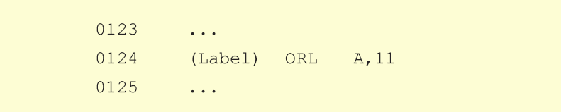
Before execution: A= C2h (11000010 Bin.)
After execution: A= C3h (11000011 Bin.)
ORL C,bit - Logical-OR operation between bit and Carry bit
C: Carry bit
bit: Any bit in RAM
Description: Instruction performs logical-OR operation (logical OR)
between the addressed bit and Carry bit. The result is stored in the Carry bit.bit: Any bit in RAM
Syntax: ORL C,bit
Bytes: 2 (Instruction Code, Bit address)
STATUS register flags: No flags affected.
EXAMPLE:

Before execution: ACC= C6h (11001010 Bin.)
C=0
After execution: C=1
ORL Rx,#X - Logical-OR operation between directly addressed register Rx and number X
Rx: Arbitrary register with address 0 - 255
(0 - FFh)
X: Constant in the range of 0 - 255 (0-FFh)
Description: Instruction performs logical-OR operation between the Rx
registers and number X. As it is direct addressing, Rx can be some of SFRs or
general-purpose register with address 0-7Fh (0-127 dec.). The result of this
logical operation is stored in the Rx register.X: Constant in the range of 0 - 255 (0-FFh)
Syntax: ORL [register address],#X
Bytes: 3 (Instruction Code, Address Rx, Constant X)
STATUS register flags: No flags affected.
EXAMPLE:

Before execution: TEMP= C2h (11000010 Bin.)
After execution: A= D2h (11010010 Bin.)
POP Rx - Pop data from Stack
Rx: Arbitrary register with address 0 - 255
(0 - FFh)
Description: Instruction first reads data from the location the Stack
Pointer is currently ponting to. Afterwards, the data is copied to the register
Rx and the value of the Stack Pointer is decremented by 1. As it is direct
addressing, Rx can be some of SFRs or general-purpose register with address
0-7Fh. (0-127 dec.)Syntax: POP Rx
Bytes: 2 (Instruction Code, Address Rx)
STATUS register flags: No flags affected.
EXAMPLE:

Before execution: Address Value
030h 20h
031h 23h
SP==> 032h 01h
DPTR=0123h (DPH=01, DPL=23h)
After execution: Address Value
SP==> 030h 20h
031h 23h
032h 01h
ORL C,/bit - Logical-OR operation between complement bit and Carry bit
C: Carry bit
bit: Any bit in RAM
Description: Instruction performs logical-AND operation (logical OR) between
addressed inverted bit and Carry bit. The result is stored in the Carry bit.bit: Any bit in RAM
bit
|
bit
|
C
|
C AND bit
|
0
|
1
|
0
|
0
|
0
|
1
|
1
|
1
|
1
|
0
|
0
|
0
|
1
|
0
|
1
|
0
|
Bytes: 2 (Instruction Code, Bit address)
STATUS register flags: No flags affected.
EXAMPLE:

Before execution: ACC= C6h (11001010 Bin.)
C=0
After execution: C=0
RET - Return from subroutine
Description: This instruction ends every subroutine. After execution, the program proceeds with the instruction currently following an ACALL or LCALL.
Syntax: RET
Byte: 1 (Instruction Code)
STATUS register flags: No flags affected.
EXAMPLE:

PUSH Rx - Push data onto Stack
Rx: Arbitrary register with address 0 - 255
(0 - FFh)
Description: Address currently pointed to by the Stack Pointer is
first incremented by 1 and afterwards the data from the register Rx are copied
to it. As it is direct addressing, Rx can be some of SFRs or general-purpose
register with address 0-7Fh. (0-127 dec.)Syntax: PUSH Rx
Bytes: 2 (Instruction Code, Address Rx)
STATUS register flags: No flags affected.
EXAMPLE:

Before execution: Address Value
SP==> 030h 20h
DPTR=0123h (DPH=01, DPL=23h)
After execution: Address Value
030h 20h
031h 23h
SP==> 032h 01h
RL A - Rotate accumulator one bit left
A: accumulator
Description: Eight bits in the accumulator are rotated one bit left,
so that the bit 7 is rotated into the bit 0 position.Syntax: RL A
Byte: 1 (Instruction Code)
STATUS register flags: No flags affected.
EXAMPLE:

Before execution: A= C2h (11000010 Bin.)
After execution: A=85h (10000101 Bin.)

RETI - Return from interrupt
Description: This instruction ends every interrupt routine and informs processor that interrupt routine is no longer in progress. After instruction execution, the execution of the interrupted program continues from where it left off. The PSW is not autotomatically restored to its pre-interrupt status.
Syntax: RETI
Byte: 1 (Instruction Code)
STATUS register flags: No flags affected.
RR A - Rotate accumulator one bit right
A: accumulator
Description: All eight bits in the accumulator are rotaded one bit
right so that the bit 0 is rotated into the bit 7 position.Syntax: RR A
Byte: 1 (Instruction Code)
STATUS register flags: No flags affected.
EXAMPLE:

Before execution: A= C2h (11000010 Bin.)
After execution: A= 61h (01100001 Bin.)

RLC A - Rotate accumulator one bit left through Carry bit
A: accumulator
Description: All eight bits in the accumulator and Carry bit are
rotated one bit left. After this operation, the bit 7 is rotated into the Carry
bit position and the Carry bit is rotated into the bit 0 position.Syntax: RLC A
Byte: 1 (Instruction Code)
STATUS register flags: C
EXAMPLE:

Before execution: A= C2h (11000010 Bin.)
C=0
After execution: A= 85h (10000100 Bin.)
C=1

SETB C - Set Carry bit
C: Carry bit
Description: Instruction sets the Carry bit.Syntax: SETB C
Byte: 1 (Instruction Code)
STATUS register flags: C
EXAMPLE:

After execution: C=1
RRC A - Rotate accumulator one bit right through Carry bit
A: accumulator
Description: All eight bits in the accumulator and Carry bit are
rotated one bit right. After this operation, the Carry bit is rotated into the
bit 7 position and the bit 0 is rotated into the Carry position.Syntax: RRC A
Byte: 1 (Instruction Code)
STATUS register flags: C
EXAMPLE:

Before execution: A= C2h (11000010 Bin.)
C=0
After execution: A= 61h (01100001 Bin.)
C=0

SJMP rel - Short Jump
adr: Jump Address
Description: Instruction enables jump to the new address that address
should be in the range of -128 to +127 locations relative to the first
following instruction.Syntax: SJMP [jump address]
Bytes: 2 (Instruction Code, Jump Value)
STATUS register flags: No flags are affected.
EXAMPLE:

Before execution: PC=323
After execution: PC=345
SETB bit - Set bit
bit: Any bit in RAM
Description: Instruction sets the specified bit. The register
including that bit must belong to the group of so called bit addressable
registers.Syntax: SETB [bit address]
Bytes: 2 (Instruction Code, Bit Address)
STATUS register flags: No flags are affected.
EXAMPLE:

Before execution: P0.1 = 34h (00110100)
pin 1 is configured as output
After execution: P0.1 = 35h (00110101)
pin 1 is configured as input
SUBB A,Rx - Subtract Rx from accumulator
Rx: Arbitrary register with address 0 - 255
(0 - FFh)
A: accumulator
Description: Instruction performs subtract operation: A-Rx including
the Carry bit as well which acts as borrow. If the higher bit is subtracted
from the lower bit then the Carry bit is set. As it is direct addressing, Rx
can be some of SFRs or general-purpose register with address 0-7Fh. (0-127
dec.). The result is stored in the accumulator.A: accumulator
Syntax: SUBB A,Rx
Bytes: 2 (Instruction Code, Address Rx)
STATUS register flags: C, OV, AC
EXAMPLE:

Before execution: A=C9h, DIF=53h, C=0
After execution: A=76h, C=0
SUBB A,Rn - Subtruct Rn from accumulator
Rn: Any R register (R0-R7)
A: accumulator
Description: Instruction performs subtract operation: A-Rn including
the Carry as well which acts as borrow. If the higher bit is subtracted from
the lower bit then the Carry bit is set. The result is stored in the
accumulator.A: accumulator
Syntax: SUBB A,Rn
Byte: 1 (Instruction Code)
STATUS register flags: C, OV, AC
EXAMPLE:

Before execution: A=C9h, R4=54h, C=1
After execution: A=74h, C=0
Note:
The result is different (C9 - 54=75!) because the Carry bit has been set (C=1)before instruction execution.
SUBB A,#X - Subtract number X from accumulator
A: accumulator
X: Constant in the range of 0 - 255 (0-FFh)
Description: Instruction performs subtract operation: A-X including
the Carry bit as well which acts as borrow. If the higher bit is subtracted
from the lower bit then the Carry bit is set. The result is stored in the
accumulator.X: Constant in the range of 0 - 255 (0-FFh)
Syntax: SUBB A,#X
Bytes: 2 (Instruction Code, Constant X)
STATUS register flags: C, OV, AC
EXAMPLE:

Before execution: A=C9h, C=0
After execution: A=A7h, C=0
SUBB A,@Ri - Subtract indirectly addressed register from accumulator
Ri: Register R0 or R1
A: accumulator
Description: Instruction performs subtract operation: A-Rx including
the Carry bit as well which acts as borrow. If the higher bit is subtracted
from the lower bit then the Carry bit is set. As it is indirect addressing,
register Rx address is located in the Ri register (R0 or R1) . The result of
the operation is stored in the accumulator.A: accumulator
Syntax: SUBB A,@Ri
Byte: 1 (Instruction Code)
STATUS register flags: C, OV, AC
EXAMPLE:

Register Address MIN=F4
Before execution: A=C9h, R1=F4h, MIN=04, C=0
After execution: A=C5h, C=0
XCH A,Rn - Exchange registers Rn with accumulator
Rn: Any R register (R0-R7)
A: accumulator
Description: Instruction causes the accumulator and Rn registers to
exchange data. The content of the accumulator is set in the register Rn. At the
same time, the content of the Rn register is set in the accumulator.A: accumulator
Syntax: XCH A,Rn
Byte: 1 (Instruction Code)
STATUS register flags: No flags are affected.
EXAMPLE:

Before execution: A=C6h, R3=29h
After execution: R3=C6h, A=29h
SWAP A - Swap nibbles within accumulator
A: accumulator
Description: A word “nibble” designates a group of 4 adjacent bits
within one register (bit0-bit3 and bit4-bit7).This instruction interchanges the
high and low nibbles of the accumulator.Syntax: SWAP A
Byte: 1 (Instruction Code)
STATUS register flags: No flags are affected.
EXAMPLE:

Before execution: A=E1h (11100001)bin.
After execution: A=1Eh (00011110)bin.

XCH A,@Ri - Exchange accumulator with indirectly addressed register Rx
Ri: Register R0 or R1
A: accumulator
Description: Instruction sets the contents of accumulator into
register Rx. At the same time, the content of register Rx is set into the
accumulator. As it is indirect addressing, register Rx address is located in
the register Ri (R0 or R1).A: accumulator
Syntax: XCH A,@Ri
Byte: 1 (Instruction Code)
STATUS register flags: No flags are affected.
EXAMPLE:

Register Address SUM=E3
Before execution: R0=E3, SUM=29h, A=98h
After execution: A=29h, SUM=98h
XCH A,Rx - Exchange the content of registers Rx with the content of accumulator
Rx: Arbitrary register with address 0 - 255
(0 - FFh)
A: accumulator
Description: Instruction sets the contents of the accumulator into
the register Rx. At the same time, the content of the Rx register is set into
the accumulator. As it is direct addressing, the register Rx can be some of
SFRs or general-purpose register with address 0-7Fh (0-127 dec.).A: accumulator
Syntax: XCH A,Rx
Bytes: 2 (Instruction Code, Address Rx)
STATUS register flags: No flags are affected.
EXAMPLE:

Before execution: A=FFh, SUM=29h
After execution: SUM=FFh A=29h
XRL A,Rn - Exclusive-OR operation between register Rn and accumulator
Rn: Any R register (R0-R7)
A: accumulator
Description: Instruction performs exclusive-OR operation between the
accumulator and Rn register. The result of this logical operation is stored in
the accumulator.A: accumulator
Syntax: XRL A,Rn
Byte: 1 (Instruction Code)
STATUS register flags: No flags are affected.
EXAMPLE:

Before execution: A= C3h (11000011 Bin.)
R3= 55h (01010101 Bin.)
After execution: A= 96h (10010110 Bin.)
XCHD A,@Ri - Exchange the content of low nibbles accumulator with indirectly addressed register Rx
Ri: Register R0 or R1
A: accumulator
Description: This instruction interchanges the low nibbles (bits 0-3)
of the accumulator with the low nibbles of indirectly addressed register Rx.
High nibbles of the accumulator and Rx register are not affected. This
instruction is mainly used in operating with BCD values. As it is indirect
addressing, the regiter Rx address is stored in the register Ri (R0 or R1).A: accumulator
Syntax: XCHD A,@Ri
Byte: 1 (Instruction Code)
STATUS register flags: No flags are affected.
EXAMPLE:

Register Address SUM=E3
Before execution: R0=E3 SUM=29h A=A8h,
After execution: A=A9h, SUM=28h

XRL A,@Ri - Exclusive-OR operation between accumulator and indirectly addressed register
Ri: Register R0 or R1
A: accumulator
Description: Instruction performs exclusive-OR operation between the
accumulator and Rx register. As it is indirect addressing, register Rx address
is stored in the Ri register (R0 or R1). The result of this logical operation
is stored in the accumulator.A: accumulator
Syntax: XRL A,@Ri
Byte: 1 (Instruction Code)
STATUS register flags: No flags are affected.
EXAMPLE:

Register Address TEMP=FAh, R1=FAh
Before execution: TEMP= C2h (11000010 Bin.)
A= 54h (01010100 Bin.)
After execution: A= 96h (10010110 Bin.)
XRL A,Rx - Exclusive-OR operation between accumulator and register Rx
Rx: Arbitrary register with address 0 - 255
(0 - FFh)
A: accumulator
Description: Instruction performs exclusive-OR operation between the
accumulator and Rx Register. As it is direct addressing, the Rx register can be
some of SFRs or general-purpose register with address 0-7Fh (0-127 dec.). The
result of this logical operation is stored in the accumulator.A: accumulator
Syntax: XRL A,Rx
Bytes: 2 (Instruction Code, Address Rx)
STATUS register flags: No flags are affected.
EXAMPLE:

Before execution: A= C2h (11000010 Bin.)
LOG= 54h (01010100 Bin.)
After execution: A= 96h (10010110 Bin.)
XRL Rx,A - Exclusive-OR operation between directly addressed register Rx and accumulator
Rx: Arbitrary register with address 0 - 255
(0 - FFh)
A: accumulator
Description: Instruction performs exclusive-OR operation between the
Rx Register and accumulator. As it is direct addressing, the Rx register can be
some of SFRs or general-purpose register with address 0-7Fh (0-127 dec.). The
result of this logical operation is stored in the Rx register.A: accumulator
Syntax: XRL Rx,A
Bytes: 2 (Instruction Code, Address Rx)
STATUS register flags: No flags are affected.
EXAMPLE:

Before execution: TEMP= C2h (11000010 Bin.)
A= 54h (01010100 Bin.)
After execution: A= 96h (10010110 Bin.)
XRL A,#X - Exclusive-OR between accumulator and number X
X: Constant in the range of 0 - 255 (0-FFh)
A: accumulator
Description: Instruction performs exclusive-OR operation between the
accumulator and number X. The result of this logical operation is stored in the
accumulator.A: accumulator
Syntax: XRL A,#X
Bytes: 2 (Instruction Code, Constant X)
STATUS register flags: No flags are affected.
EXAMPLE:

Before execution: A= C2h (11000010 Bin.)
X= 11h (00010001 Bin.)
After execution: A= D3h (11010011 Bin.)

Rx: Arbitrary register with address 0 - 255
(0 - FFh)
X: Constant in the range of 0 - 255 (0-FFh)
Description: Instruction performs exclusive-OR operation between the
Rx Register and number X. As it is direct addressing, the Rx register can be
some of SFRs or general-purpose register with address 0-7Fh (0-127 dec.). The
result of this logical operation is stored in the Rx register.X: Constant in the range of 0 - 255 (0-FFh)
Syntax: XRL Rx,#X
Bytes: 3 (Instruction Code, Address Rx, Constant X)
STATUS register flags: No flags are affected.
EXAMPLE:
Before execution: TEMP= C2h (11000010 Bin.)
X=12h (00010010 Bin.)
After execution: A= D0h (11010000 Bin.)
No comments:
Post a Comment